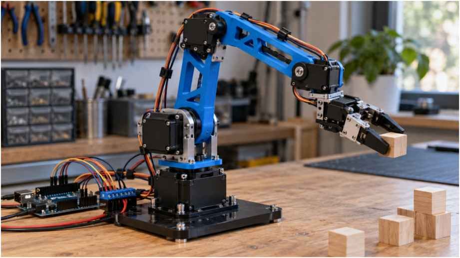
Building my first DIY robotic arm project taught me a hard truth within thirty seconds of powering up: software bugs freeze code, but electrical shortcuts burn hardware. My initial 4-axis assembly immediately shuddered, brown-outed my Arduino Uno, and stripped a nylon micro-servo gear before the gripper even closed around a wooden block. Most starter guides gloss over basic joint physics and current surges, leaving makers confused when their robotic arm crashes.
I redesigned my setup from scratch, swapping cheap undersized servos for metal gear units, isolating the power distribution, and calculating the exact joint torque requirements beforehand.
Anatomy of an Articulated Arm: Components That Actually Hold Up
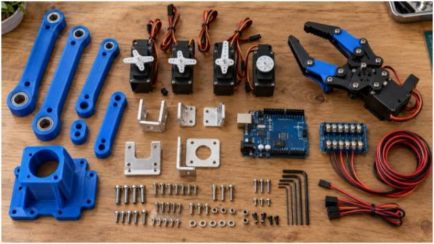
A standard multi-axis manipulator relies on three core elements: structural links, rotational actuators, and a central controller. Budget kits often market all-in-one acrylic frames, but thin laser-cut acrylic flexes under load. I prefer 3D-printed PETG or rigid 3mm anodized aluminum chassis parts. PETG resists the layer-shear stresses caused by dynamic arm movements better than standard PLA.
+————————————————————-+
| Power Supply (5V/5A) |
+——————————+——————————+
|
+——————+——————+
| (+) 5V Rail | (-) Ground
v v
+—————–+ +—————–+
| 4-6x Servos | | Arduino Uno |
| (VCC Terminal) | | (GND Pin) |
+——–+——–+ +——–+——–+
^ |
| PWM Signals |
+————————————-+
Selecting Servos Without Stripping Nylon Gears
Actuators form the muscle of your arm. The common blue SG90 9g micro-servo is fine for opening and closing a lightweight claw. However, using an SG90 on the base pan or shoulder pitch joint invites immediate gear failure. The tiny nylon gears strip under minimal shear stress.
For the shoulder and elbow, I run digital MG996R or DS3218 metal-gear servos. The MG996R provides roughly 10 kg-cm of holding torque at 6V, while the DS3218 pushes past 20 kg-cm. Running brass or steel gear trains prevents internal tooth breakage when the arm comes to an abrupt stop.
Microcontroller Options and Breadboard Power Routing
An Arduino Uno R3 handles positional PWM control cleanly across six servo channels via its dedicated timers. You can swap this for an Arduino Nano if you need a compact footprint.
The biggest pitfall is power distribution. Standard breadboard power rails use thin spring clips that cannot pass high current. When two MG996R servos swing simultaneously, bench tests show stall current spikes reaching 2.8A.
Standard USB ports output 0.5A to 1A max, and the Arduino onboard 5V regulator burns out if overloaded. Use a dedicated external 5V to 6V, 5A DC power supply. Wire your power supply leads directly to a terminal distribution block, splice the ground to your Arduino GND, and run clean, isolated DC current to your motor pins.
Joint Torque Physics: The Math Most Tutorials Skip
Mechanical failure happens when joint torque exceeds motor holding ratings. Torque () equals force multiplied by the perpendicular distance from the pivot point:
=Fr=(mg)r
Where m is mass, g is gravitational acceleration (9.81m/s2), and r is the extended radius (lever arm length).
Cantilever Calculations for Shoulder and Elbow Joints
Consider a horizontal arm reach of 20 centimeters with a payload of 100 grams (0.1 kg) at the gripper. You must also account for the mass of the arm segments and the motors themselves.
- Gripper and payload mass: 180g (1.77N) at $20\text{ cm} \rightarrow 3.54\text{ kg}\cdot\text{cm}$
- Forearm segment + wrist servo mass: 120g center of mass at $12\text{ cm} \rightarrow 1.44\text{ kg}\cdot\text{cm}$
- Upper arm segment mass: 80g center of mass at $5\text{ cm} \rightarrow 0.40\text{ kg}\cdot\text{cm}$
Summing these static torques at the shoulder pivot yields:
$$3.54 + 1.44 + 0.40 = 5.38\text{ kg}\cdot\text{cm}$$
Dynamic movements and rapid acceleration increase torque demand. Applying a safety factor of 2.5 to the calculated static torque gives:
Required torque = 5.38 kgf·cm × 2.5 = 13.45 kgf·cm
An SG90 rated at approximately 1.8 kgf·cm is undersized for this load. An MG996R rated at approximately 10 kgf·cm also falls below the target, while a DS3218 rated above 20 kgf·cm provides sufficient rated torque, assuming the specified operating voltage.
Step-by-Step Build and Wiring Protocol
Assembling the physical arm requires strict ordering. Rushing to bolt links together leads to misaligned joint ranges that require complete disassembly later.
[Claw / End Effector] (SG90 Servo)
|
[Wrist Pitch / Roll] (SG90 or MG90S)
|
[Forearm Link] (10-12 cm)
|
[Elbow Joint] (MG996R Servo)
|
[Bicep Link] (10-12 cm)
|
[Shoulder Joint] (MG996R Servo)
|
[Base Turntable / Yaw] (MG996R + Thrust Bearing)
Mechanical Zeroing Before Assembly
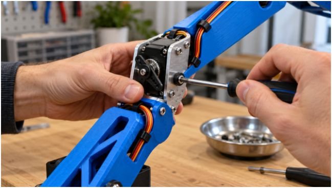
Never mount a servo horn to a joint linkage out of the box. Servos rotate through a fixed arc—typically 0 to 180 degrees. If you screw on a bracket when the internal potentiometer sits at 0 degrees, driving the joint backward forces the motor against its internal mechanical stop, breaking the gearbox.
Flash your Arduino with a basic calibration script using the native <Servo.h> library. Write a command sending all active channels to 90 degrees:
C++
#include <Servo.h>
Servo baseServo, shoulderServo, elbowServo, clawServo;
void setup() {
baseServo.attach(3);
shoulderServo.attach(5);
elbowServo.attach(6);
clawServo.attach(9);
baseServo.write(90);
shoulderServo.write(90);
elbowServo.write(90);
clawServo.write(90);
}
void loop() {
// Hold center position for physical alignment
}
Power the board, let every output shaft seek its electrical midpoint, and only then mount the physical servo horns so each joint sits squarely at the midpoint of its travel.
Electrical Assembly and Common-Ground Isolation
Run separate paths for signal and drive power. High-current motor return paths generate transient noise on the ground rail, which can corrupt the Arduino analog-to-digital converter (ADC) readings. Engineering guidelines from All About Circuits stress that star grounding topologies resolve ground loops in hobbyist mechatronics.
- Connect the external 5V positive lead directly to the red VCC servo leads.
- Connect the external supply negative terminal to a central ground distribution rail.
- Bridge that common ground rail directly to an Arduino GND pin using a short, thick lead.
- Route each yellow or orange signal wire from Arduino PWM pins (3, 5, 6, 9, 10, 11) to the motor control lines.
- Solder a 1000 µF, 16V electrolytic capacitor across the external 5V and GND rail near the motors to absorb inductive kickback.
Programming Motion Control and Coordinate Smoothing
Basic code maps potentiometer analog inputs directly to servo angles using servo.write(map(analogRead(pin), 0, 1023, 0, 180)). While this responds quickly, sudden jumps snap the arm links and cause erratic wobble.
Professional kinematics platforms, such as NASA JPL Open Source Rover projects, implement ramped velocity profiles. You can achieve this simply in Arduino code by stepping toward target coordinates with a non-blocking timing loop:
C++
void moveToPosition(Servo &motor, int targetAngle, int currentAngle, int stepDelay) {
if (targetAngle > currentAngle) {
for (int pos = currentAngle; pos <= targetAngle; pos++) {
motor.write(pos);
delay(stepDelay);
}
} else {
for (int pos = currentAngle; pos >= targetAngle; pos–) {
motor.write(pos);
delay(stepDelay);
}
}
}
Adding a 15-millisecond delay between single-degree steps reduces mechanical jerk, preserves internal servo gears, and stops the base from tipping over during high-speed swings.
Troubleshooting Jitter, Stall Slump, and Reset Loops
If your arm twitches uncontrollably when stationary, check your input signal isolation. Potentiometers pick up high-frequency EMI if routed parallel to unshielded servo power cables. Twist your motor power lines into pairs to suppress noise.
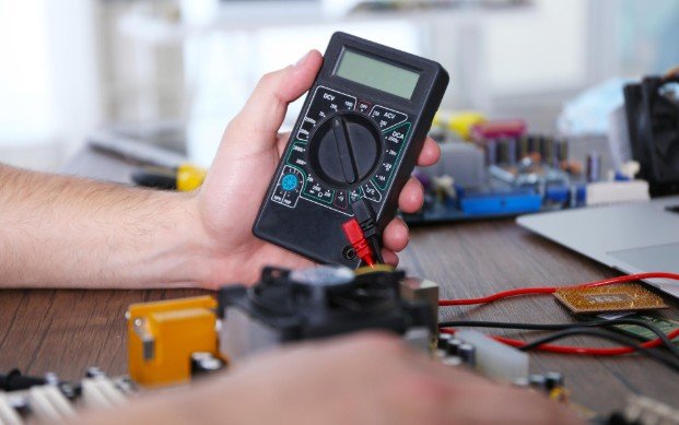
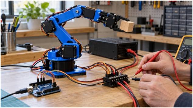
If the microcontroller resets the moment the arm lifts a payload, your servos are pulling the external supply rail below the 4.5V threshold. Place your multimeter in peak-hold mode across the power rails to verify your supply voltage under full load.
When a joint slowly sags despite commanding a hold angle, your static load exceeds the servo’s holding torque rating. You must counter-balance the assembly using extension springs or counterweights, or upgrade to a higher-torque actuator.
If you have already built a basic obstacle avoiding robot build or cut your teeth tuning an infrared line follower robot, an articulated arm is your natural next step. This project demands careful attention to payload physics, wiring architecture, and mechanical stability.
Frequently Asked Questions About Building a Robotic Arm
1. What is the best power supply for a 4-DOF Arduino robotic arm?
A regulated 5V or 6V DC switching power supply delivering at least 4 to 5 amps of steady current.
2. Can I control a DIY robotic arm project using Python?
You can stream coordinate arrays over USB serial from a Python script using the pySerial library to an Arduino motion controller.
3. Why do my robotic arm servos vibrate and hum when stationary?
Servos hum when fighting external gravity loads, hunting between potentiometer feedback values, or suffering from voltage sag on an undersized power rail.
4. What is the difference between 4-DOF and 6-DOF robotic arms?
A 4-DOF arm manages 3D position with limited tool tilt, while a 6-DOF arm provides full Cartesian spatial positioning (X, Y, Z) plus roll, pitch, and yaw orientations.
Quit Stalling and Wire It Up
Your workbench is ready, your torque calculations balance out, and the hardware limits are clear. Skip the hot-glue short-cuts, wire up a clean external power rail with a shared ground, and bolt your joints together with calibrated metal gears.
Once your basic 4-axis arm can reliably pick and place a payload on command, you can mount an ultrasonic sensor, integrate inverse kinematics algorithms, or add a computer vision tracking pipeline. Grab your hex keys, fire up your soldering iron, and get building.