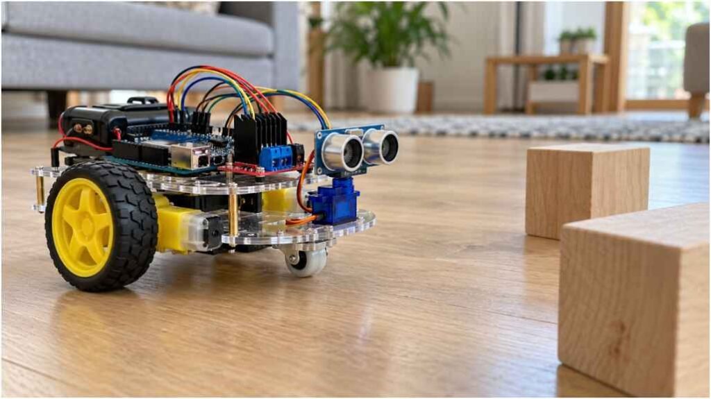
Every successful autonomous rover starts with a dependable sensor-to-actuator control loop. During my first obstacle avoiding robot build, my bot repeatedly rammed straight into baseboards because of electrical brownouts rather than bad navigation logic.
Designing an autonomous robot demands tight coordination between power distribution, sensor calibration, and drive-wheel physics. A sudden stall current from small gear motors or panning servos can drop the logic voltage on an MCU board below its threshold, corrupting distance readings mid-transit. Resolving these electrical challenges turns a fragile toy into a reliable rover that maneuvers around any obstacle in its path.
Robot Power Distribution
| Power Source or Connection | Destination | Purpose |
| Two 18650 cells in series: 7.4V nominal, 8.4V fully charged | L298N motor supply input | Supplies the motor driver; ensure the voltage reaching the motors stays within their rating |
| Battery positive (+) | Buck converter input (+) | Supplies the step-down converter |
| Buck converter regulated 5V output | Arduino Uno 5V pin | Supplies regulated power to the controller; do not connect this 5V supply to VIN |
| Buck converter regulated 5V output | HC-SR04 VCC | Powers the ultrasonic sensor |
| Buck converter regulated 5V output | SG90 positive power lead | Powers the servo; size the converter for the combined load and servo current spikes |
| Arduino control pins | L298N ENA, ENB, and IN1–IN4 | Controls motor speed and direction |
| Arduino trigger output and echo input | HC-SR04 Trig and Echo | Sends the trigger pulse and reads the distance signal |
| Arduino servo signal output | SG90 signal lead | Controls the sensor’s scanning angle |
| Battery negative (−) | Buck converter input ground, output ground, L298N GND, Arduino GND, HC-SR04 GND, and SG90 ground | Establishes a common ground reference |
Correction: 7.4V is the battery pack’s nominal voltage; 8.4V is its fully charged voltage. This layout powers the Arduino, sensor, and servo from the regulated buck converter. Leave the L298N’s 5V output disconnected from that shared 5V rail.
Sourcing the Hardware and Core Architecture
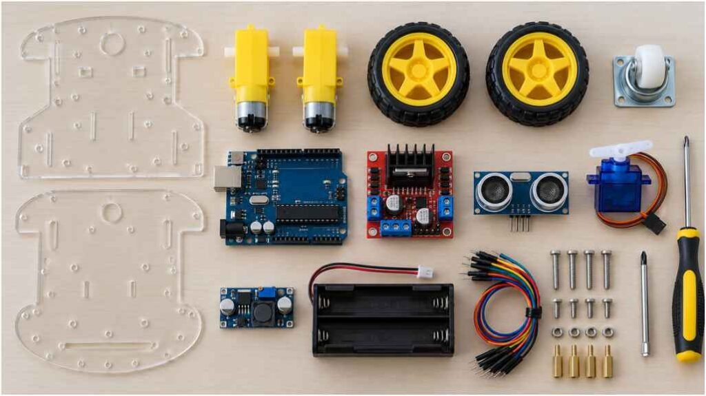
My standard platform runs on a 2WD acrylic chassis featuring twin 3V–6V yellow TT spur gear motors, a front-mounted passive caster, and an Arduino Uno as the primary controller.
The sensory hub uses an HC-SR04 ultrasonic transducer mounted atop an SG90 micro servo. This mechanical pairing lets the sensor sweep a 180-degree field of view without rotating the entire chassis.
Driving the drive wheels directly from microcontrollers burns out output stages. Instead, an L298N dual H-bridge motor driver acts as the heavy-current intermediary between your battery pack and the motors.
Logic, Sensing, and Motor Drive Specs
The L298N features an internal LM7805 voltage regulator. When you feed 7.4V to 12V into its power terminal, you can leave its onboard 5V logic jumper engaged to power its internal logic gates.
For the power source, avoid low-capacity 9V alkaline transistor batteries. They lack the peak discharge current necessary for simultaneous motor rotation and sensor sweeps. Two unprotected 18650 lithium-ion cells in series deliver 7.4V nominal (8.4V fully charged), easily supplying the 1.2A to 2A bursts required by small DC gearboxes.
| Component | Operating Voltage | Peak Current Draw | Primary Function |
| Arduino Uno | 5V (USB or 7–12V VIN) | ~50 mA | Decision-making logic and PWM signal output |
| L298N Dual H-Bridge | 5V Logic, 7–12V Motor Rail | Up to 2A per channel | Motor direction and speed control |
| HC-SR04 Sensor | 5V DC | 15 mA active | Ultrasonic distance measurement |
| SG90 Micro Servo | 4.8V – 6V DC | ~250 mA stall | Sweeps sensor left, right, and center |
| TT Gear Motors (x2) | 3V – 6V DC | 400–800 mA each stall | Differential wheel propulsion |
The Ground Loop and Brownout Trap
The most common failure in any novice autonomous build is an uncontrolled microcontroller reboot. You power the robot, it moves forward for two seconds, turns its servo, and suddenly resets back to its initialization tone.
DC motors generate substantial electrical noise and back-EMF spikes when they engage or reverse polarity. According to Texas Instruments engineering specifications, switching inductive loads causes severe localized electromagnetic interference and transient voltage drops across shared DC supply lines unless decoupling steps are taken.
Benchmarking the SG90 Servo Inrush Voltage Drop
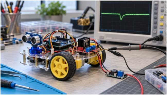
To track down these mysterious resets, I connected an oscilloscope to the Arduino’s 5V rail during an autonomous run. The Arduino Uno’s onboard linear regulator maintains a steady 5.01V under idle conditions.
When the SG90 servo abruptly sweeps 90 degrees while the drive wheels run, inrush current draws cause a sharp 12-millisecond drop, dragging the logic rail down to 4.18V.
Supply Rail (V)
5.0V |————————–\ /—————–
| \ /
4.5V | \ /
| Brownout Trigger (4.3V) –\———-/–
4.0V | \________/ <- 4.18V Drop (Reset Occurs)
|
+————————————————————> Time (ms)
[Servo Inrush Period: ~12ms]
This 4.18V trough dips straight past the ATmega328P microcontroller’s Brown-Out Detection (BOD) floor of 4.3V. The microcontroller triggers a hard reset to protect register memory from corruption.
Fix this issue by powering the SG90 servo and HC-SR04 from an independent 5V buck converter connected directly to your battery pack. Never power a servo from the Arduino’s 5V pin.
Tie every ground line together—battery ground, driver ground, buck converter ground, and Arduino ground. A common reference plane keeps your PWM control signals clean and readable.
Step-by-Step Electrical Assembly and Pin Configuration
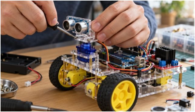
Assemble the robot systematically, wiring each subsystem before securing the chassis frame:
- Mount the Motors and Running Gear: Bolt the two DC gear motors to the lower chassis plate. Slide the rubber wheels over the dual-flat shafts and screw the front swivel caster wheel in place.
- Mount the Servo and Transducer: Secure the SG90 servo motor dead-center on the front upper chassis with its splined shaft facing skyward. Center the servo horn in software at 90 degrees before snapping the HC-SR04 bracket onto the output spline.
- Wire the Logic and Drive Subsystems: Run signal wires from your microcontroller to the driver board and sensor array using the pinout configurations detailed below.
Arduino Uno Wiring Connections
| Component | Component Pin | Connection | Function |
| HC-SR04 Sensor | VCC | Regulated 5V supply | Sensor power |
| HC-SR04 Sensor | Trig | Arduino D11 | Sends the ultrasonic trigger pulse |
| HC-SR04 Sensor | Echo | Arduino D12 | Reads the returning echo pulse |
| HC-SR04 Sensor | GND | Common ground | Ground reference |
| L298N Driver | ENA | Arduino D9 | Left motor speed control |
| L298N Driver | IN1 | Arduino D8 | Left motor direction control |
| L298N Driver | IN2 | Arduino D7 | Left motor direction control |
| L298N Driver | IN3 | Arduino D6 | Right motor direction control |
| L298N Driver | IN4 | Arduino D5 | Right motor direction control |
| L298N Driver | ENB | Arduino D3 | Right motor speed control |
| SG90 Servo | Signal | Arduino D10 | Controls the scanning angle |
| SG90 Servo | Positive power lead | Regulated 5V buck converter output | Servo power |
| SG90 Servo | Ground lead | Common ground | Ground reference |
| Component | Component Pin | Target MCU Connection | Signal Function |
| L298N Driver | ENA | Digital Pin 9 (PWM) | Left Motor Speed Enable |
| L298N Driver | IN1 | Digital Pin 8 | Left Motor Direction Bit 1 |
| L298N Driver | IN2 | Digital Pin 7 | Left Motor Direction Bit 2 |
| L298N Driver | IN3 | Digital Pin 6 | Right Motor Direction Bit 1 |
| L298N Driver | IN4 | Digital Pin 5 | Right Motor Direction Bit 2 |
| L298N Driver | ENB | Digital Pin 3 (PWM) | Right Motor Speed Enable |
| HC-SR04 | Trig | Digital Pin 11 | 10-Microsecond Pulse Trigger |
| HC-SR04 | Echo | Digital Pin 12 | Ultrasonic Return Wave Input |
| SG90 Servo | Signal (Orange) | Digital Pin 10 (PWM) | Angular Sweep Command |
Software Architecture: Time-of-Flight Logic Loop
The firmware relies on basic time-of-flight physics. The HC-SR04 emits an eight-cycle sonic burst at 40 kHz through its transmitter horn.
That high-frequency acoustic wave moves outward, bounces off the nearest dense object, and excites the receiver transducer. The echo pin outputs a logic HIGH pulse whose duration matches the sound wave’s round-trip travel time.
Based on velocity standards documented by the National Institute of Standards and Technology (NIST), sound travels through dry air at 20°C at roughly 343 meters per second (0.0343 centimeters per microsecond).
Because sound travels from the robot to the obstacle and back, divide that measured duration by two:
$$\text{Distance (cm)} = \frac{\text{Echo Pulse Duration } (\mu\text{s}) \times 0.0343}{2}$$
C++
#include <Servo.h>
const int trigPin = 11;
const int echoPin = 12;
const int enA = 9;
const int in1 = 8;
const int in2 = 7;
const int in3 = 6;
const int in4 = 5;
const int enB = 3;
Servo scanServo;
void setup() {
pinMode(trigPin, OUTPUT);
pinMode(echoPin, INPUT);
pinMode(enA, OUTPUT);
pinMode(in1, OUTPUT);
pinMode(in2, OUTPUT);
pinMode(in3, OUTPUT);
pinMode(in4, OUTPUT);
pinMode(enB, OUTPUT);
scanServo.attach(10);
scanServo.write(90);
delay(500);
}
long readDistance() {
digitalWrite(trigPin, LOW);
delayMicroseconds(2);
digitalWrite(trigPin, HIGH);
delayMicroseconds(10);
digitalWrite(trigPin, LOW);
long duration = pulseIn(echoPin, HIGH, 30000); // 30ms timeout prevents hangs
if (duration == 0) return 400; // Return safe default if sensor times out
return (duration * 0.0343) / 2;
}
void setMotors(int leftSpeed, int rightSpeed) {
analogWrite(enA, abs(leftSpeed));
analogWrite(enB, abs(rightSpeed));
digitalWrite(in1, leftSpeed > 0 ? HIGH : LOW);
digitalWrite(in2, leftSpeed < 0 ? HIGH : LOW);
digitalWrite(in3, rightSpeed > 0 ? HIGH : LOW);
digitalWrite(in4, rightSpeed < 0 ? HIGH : LOW);
}
void loop() {
long centerDist = readDistance();
if (centerDist > 30) {
setMotors(180, 180); // Move forward smoothly
} else {
setMotors(0, 0); // Stop immediately
delay(150);
scanServo.write(150); // Look Left
delay(350);
long leftDist = readDistance();
scanServo.write(30); // Look Right
delay(400);
long rightDist = readDistance();
scanServo.write(90); // Return to center
delay(250);
if (leftDist > rightDist && leftDist > 25) {
setMotors(-160, 160); // Spin left on axis
delay(350);
} else if (rightDist >= leftDist && rightDist > 25) {
setMotors(160, -160); // Spin right on axis
delay(350);
} else {
setMotors(-180, -180); // Reverse away from dead ends
delay(400);
}
}
}
Calibrating Acoustic Returns and Edge Detection
Ultrasonic sensors hit operational limits when encountering soft fabrics, acoustic baffles, or sharp angled surfaces.
If an obstacle sits at an angle greater than 45 degrees relative to your rover’s travel axis, the 40 kHz sound wave often bounces away rather than echoing back into the receiver horn. This causes the sensor to read the space as clear path.
To prevent high-speed collisions caused by angled walls, place your primary detection threshold between 25 and 35 centimeters.
This window gives the robot plenty of distance to brake and turn before its chassis clips an unseen obstruction.
[40 kHz Transmit Wave]
Robot ==========================> \ (Angled Wall > 45°)
\
\ [Deflected Sound Wave – No Echo]
v
(Object registers as clear air!)
Next-Level Autonomous Navigation
Once your rover steers clear of everyday household furniture, upgrade its control logic to make it smarter.
You can mount dual infrared tracking sensors along the lower chassis plate to transform your chassis into a DIY line follower robot whenever it meets floor markers.
To expand past basic ultrasonic sensing, consider adding an optical Time-of-Flight (ToF) sensor like the VL53L0X. Using laser light rather than acoustic pings eliminates soft-surface reflection errors, turning your rover into a nimble exploration bot.
Frequently Asked Questions
1. Why does my robot constantly spin in circles instead of driving straight?
One of your DC motors is wired backward relative to its partner; reverse the polarity on the out-of-phase motor terminals.
2. What is the maximum obstacle detection distance for the HC-SR04 sensor?
The sensor detects objects out to 400 centimeters, but returns become unreliable beyond 200 centimeters in real-world DIY builds.
3. Can I run my obstacle avoiding robot directly on a single 9V transistor battery?
No, 9V alkaline batteries feature high internal resistance and cannot output the current spikes needed by drive motors.
4. Why does the Arduino Uno restart every time the front servo sweeps?
The servo pulls more current than the Arduino’s onboard 5V regulator can supply; isolate the servo onto an independent 5V power bus.