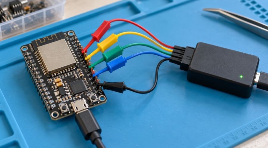
Your serial monitor says the code ran, but your sensor still refuses to respond. I’d reach for a logic analyzer before adding another page of print statements.
The best logic analyzer for debugging arduino and esp32 projects depends on your fastest signal and debugging needs. My budget choice is a supported 24 MS/s USB analyzer. I’d choose Saleae Logic 8 for its polished workflow, or Digilent Digital Discovery for faster signals and more channels.
A spare Raspberry Pi Pico offers another route, provided you accept firmware setup and unprotected GPIO inputs.
My Shortlist: Which Analyzer Should You Choose?
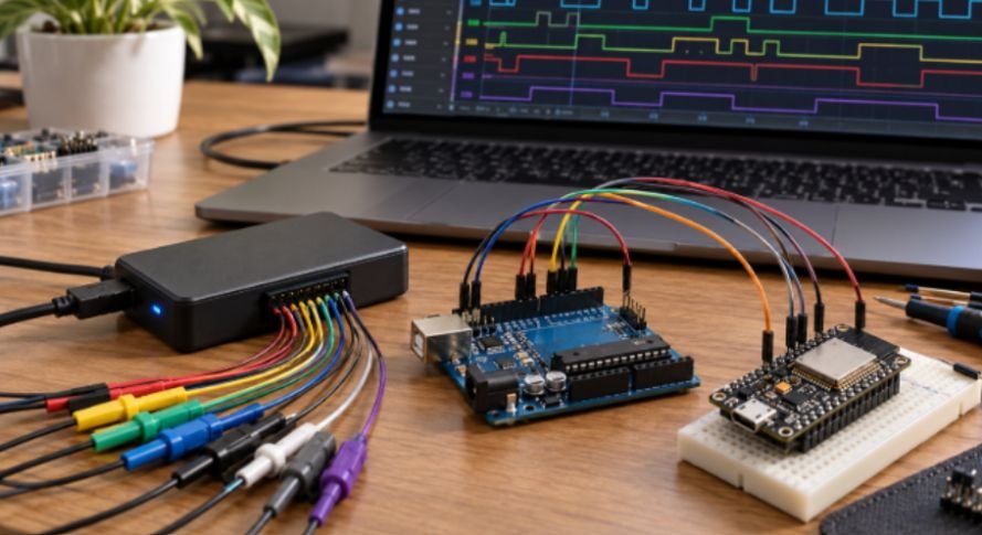
Generic 24 MS/s USB Analyzer: Budget Pick
For basic sensor projects, I’d start with a supported eight-channel USB analyzer running PulseView.
These small devices capture digital states and decode communication protocols. The sigrok hardware documentation describes the common eight-channel, 24 MHz sample-rate design. However, similar-looking products can use different hardware. Confirm compatibility before ordering.
I’d use this class of tool for 100–400 kHz I2C, ordinary UART traffic, and slower SPI buses.
The main compromises involve probes, input protection, driver setup, and vendor support. Never assume an unknown unit accepts 5V signals.
Also, “24 MHz” describes sampling speed here. It does not mean reliable decoding of a 24 MHz clock.
Saleae Logic 8: Premium Workflow Pick
I’d choose Saleae when repeated debugging makes software convenience worth paying for.
The Saleae Logic 8 specifications list eight inputs supporting digital and analog recording. Maximum rates are 100 MS/s digital and 10 MS/s analog. These are shared physical inputs, rather than sixteen separate probes. Logic 2 adds protocol decoding, searchable results, exports, and an automation API.
Its listed price is $499, although stock and checkout pricing can change.
The analog feature can help investigate slower voltage behavior alongside digital events. However, its specified analog bandwidth is 1 MHz. I would use a suitable oscilloscope for fast ringing or brief power disturbances.
My reason to upgrade would be faster investigation, easier capture sharing, and less friction between finding and explaining a fault.
Digilent Digital Discovery: High-Speed Digital Pick
I’d choose Digital Discovery when channel count, faster digital capture, or pattern generation matters most.
The Digilent product page specifies 32 channels at 200 MS/s, 16 at 400 MS/s, or eight at 800 MS/s. The higher rates require the appropriate high-speed connection hardware. It also includes a 16-channel pattern generator.
The page currently lists a $229 starting price; check the selected adapter bundle before comparing costs.
Its configurable logic levels help match supported digital systems. They do not turn its outputs into safe 5V signals for an ESP32.
Unlike Saleae Logic 8, this is a digital instrument. Choose it for digital timing and stimulus generation rather than analog waveform viewing.
Sample Rate for I2C, SPI, and UART Debugging
I choose sampling speed from the actual bus clock—not the processor’s clock frequency.
An ESP32 running at hundreds of megahertz might communicate with a sensor over 100 kHz I2C. That transaction needs far less capture speed.
My starting rule is roughly ten samples per clock cycle when practical. This provides useful timing detail, although it is not a guarantee for every waveform.
Here is a calculated example using a 24 MS/s analyzer:
| Signal clock | Samples per clock cycle | Practical interpretation |
| 400 kHz I2C | 60 | Plenty of timing detail for routine decoding |
| 4 MHz SPI | 6 | Potentially useful with clean wiring |
| 10 MHz SPI | 2.4 | Too little margin for dependable investigation |
The calculation is simple: sample rate divided by signal frequency.
This explains why a cheap analyzer can diagnose an I2C address problem yet struggle with a faster SPI display.
For UART, use the baud rate to estimate samples per bit. At 115,200 baud, even 2 MS/s provides about 17 samples per bit.
Capture duration deserves equal attention. One million samples at 20 MS/s covers only 50 milliseconds. That can miss a sensor transaction occurring once per second.
For intermittent problems, I’d lower the sample rate where appropriate, extend the recording, or trigger on the relevant event.
Raspberry Pi Pico Logic Analyzer With PulseView
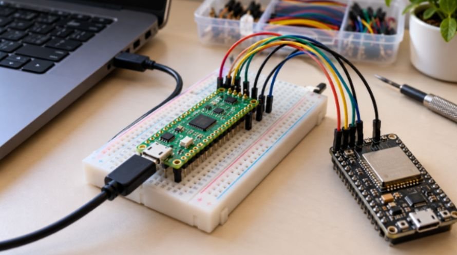
A spare Pico makes sense when learning matters as much as convenience.
The sigrok-pico project documents a baseline configuration with 21 digital channels and three analog channels. Other firmware variants change the channel arrangement. The project also states that PulseView 0.4.2 lacks support. Use a build containing the Pico driver.
Flash and Connect the Pico
Download pico_baseline.uf2 from the project’s release directory. Hold BOOTSEL while connecting the original RP2040 Pico through a USB data cable.
Copy the file onto the RPI-RP2 drive. After restarting, select the Pico driver and its serial port in PulseView.
For the baseline firmware, digital channels D2–D22 correspond to GP2–GP22. Analog inputs use GP26–GP28. Connect a Pico ground pin to your circuit’s ground.
Start with two digital channels and a modest sampling rate. Confirm a known signal before expanding the capture.
The original Pico’s GPIO inputs are not 5V tolerant. Use suitable voltage translation for 5V Arduino signals. A divider may suit slower signals, but its resistance and capacitance can distort faster edges.
I would treat Pico analog capture as a learning feature, rather than a replacement for a protected oscilloscope.
Safe Wiring and Your First Useful Capture
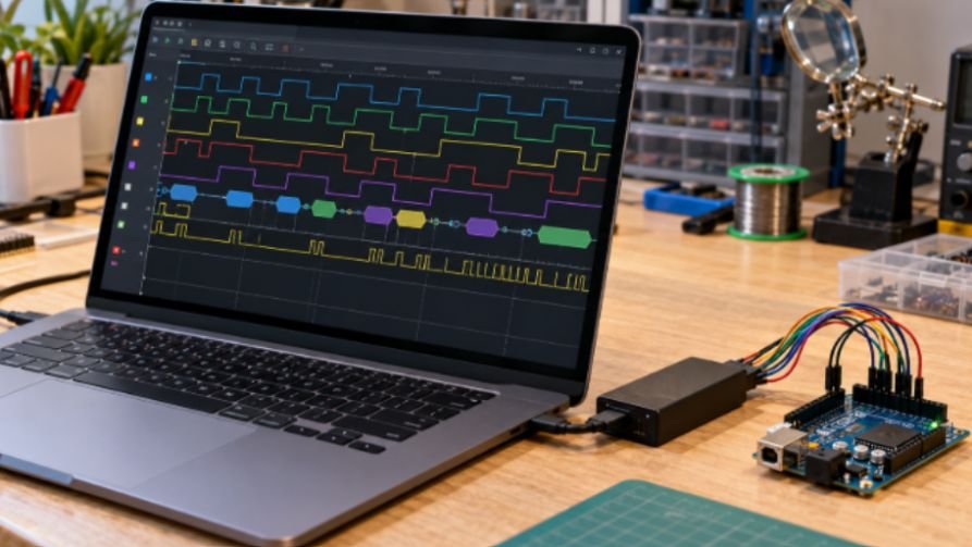
I’d begin with one repeatable transaction, such as reading a sensor register.
Connect ground first. For I2C, attach channels to SDA and SCL. For SPI, monitor clock, chip select, and the data lines you need.
Keep leads short and confirm the analyzer’s input limits. Never attach logic probes directly to motor terminals or pump power wiring.
On a plant watering system using esp32, I’d capture sensor communication alongside the pump-control signal. That can reveal whether communication stops when switching occurs. A digital capture alone cannot prove a power dip.
On a robot chassis with arduino, I’d compare command signals and PWM timing. Measuring motor voltage requires a suitable instrument and connection method.
In PulseView, assign the decoder’s channels carefully. Match UART baud rate and framing, or SPI clock polarity and phase.
If decoded data looks wrong, inspect the raw edges before changing firmware. Incorrect decoder settings can make healthy communication appear broken.
Save both the capture and the conditions that produced it. “Fails after pump startup” is far more useful than an unexplained screenshot.
Stop Guessing—Capture the Glitch
I’d buy the least expensive supported analyzer that comfortably captures my fastest bus.
Start with a generic unit for slow serial protocols. Choose Saleae for workflow convenience, or Digital Discovery for faster digital work.
Repurpose a Pico when setup time is part of the appeal, or explore this line follower robot without a microcontroller to see another practical approach to robot control.
Your next step is simple: capture one known-good transaction. That reference gives the next mysterious failure something concrete to argue with.
Frequently Asked Questions
1. What is the best logic analyzer for debugging arduino and esp32 projects on a budget?
A supported eight-channel, 24 MS/s USB analyzer with PulseView is a practical starting point for slower serial buses.
2. Can I use a Raspberry Pi Pico as a logic analyzer?
Yes; compatible sigrok-pico firmware and PulseView software turn an original Pico into a configurable capture device.
3. Is a 24 MS/s logic analyzer enough for ESP32 SPI?
It suits slower SPI clocks, but faster buses need more sampling margin for reliable timing analysis.
4. Do I need an oscilloscope as well?
Use an oscilloscope when you need voltage shape, ringing, noise, or power behavior beyond digital state changes.