A robot that runs perfectly on the workbench can lose power halfway through its first driving test. I would rather discover that limitation during planning than after mounting a larger battery that makes the chassis struggle.
Understanding how to estimate battery runtime for a robot starts with two quantities: usable battery energy and average power consumption. Once those figures reflect actual driving, waiting, and electronics loads, the calculation becomes far more useful.
Start With the Right Runtime Formula
Estimated runtime in hours equals usable battery energy in watt-hours divided by average battery-side power in watts.
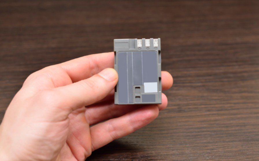
Battery energy comes from nominal voltage multiplied by capacity in amp-hours. A 7.4V battery rated at 2,200mAh holds approximately 16.28Wh because 2,200mAh equals 2.2Ah.
That energy figure allows meaningful comparisons between batteries with different voltages. Comparing mAh alone can mislead you.
The simpler formula, runtime equals usable Ah divided by average current, also works when the current represents the complete robot’s draw at the battery.
Identify Every Electrical Load
List the drive motors, motor drivers, controller, sensors, wireless modules, cameras, and accessories. Cooling fans, indicator lights, and powered USB hubs also contribute.
Record each component’s operating voltage and typical current. Datasheets provide starting values, but actual consumption depends on workload.
A motor spinning freely draws less current than one moving a loaded chassis. Likewise, a computer processing camera footage can consume more power than the same board waiting for instructions.
Convert Different Supply Voltages Into Watts
Do not directly add current drawn from different voltage rails.
A 5V sensor drawing 0.2A consumes 1W. With a converter operating at 90% efficiency, its battery-side demand becomes approximately 1.11W.
Calculate each regulated load this way, then combine the battery-side power figures. If you measure total power directly at the battery, conversion losses are already included.
Account for the Robot’s Operating Routine
Robots rarely consume constant power throughout a mission. Driving, turning, lifting, scanning, and waiting create different demands.
Estimate the fraction of time spent in each operating mode. Multiply each mode’s battery-side power by its time fraction, then add the results.
For example, driving for 60% of a mission and waiting for 40% requires a weighted average. Stationary time still consumes energy when controllers, cameras, and sensors remain active.
This duty cycle describes time spent in operating modes. It should not be confused with the motor driver’s PWM setting.
A robot’s operating routine also depends on how its control system responds to sensor inputs and changing conditions. Open-loop systems execute predefined commands without using feedback to correct their actions, whereas closed-loop systems adjust their behaviour based on measured outputs. These differences can influence motor activity, operating patterns, and overall energy consumption.
A clear understanding of the distinctions between open-loop and closed-loop robotic control systems enables more accurate assessments of how control strategies influence operational behaviour and energy consumption under real-world conditions.
A robot’s operating performance also depends on the structural properties of its chassis. A rigid frame can help maintain component alignment under load, while a more flexible design may accommodate certain impacts or uneven terrain. These characteristics can influence mechanical stability, propulsion demands, and energy use during operation.
Evaluating the structural characteristics of a rigid versus flexible robot chassis provides valuable insight into how frame stiffness and mechanical compliance can influence a robot’s energy efficiency and battery endurance under real-world operating conditions.
Work Through a Complete Rover Example
Here is how to estimate battery runtime for a robot using a hypothetical two-motor rover.
Assume its 7.4V, 2.2Ah battery stores 16.28Wh. For this example, reserve 20% of rated energy, leaving approximately 13.02Wh usable. This is a planning assumption; the correct allowance depends on the pack and operating limits.
Suppose total battery-side power is 12W while driving and 3W while waiting.
With 60% driving time, average power equals 0.6 × 12W plus 0.4 × 3W, producing 8.4W.
Divide 13.02Wh by 8.4W. Estimated runtime is approximately 1.55 hours, or 93 minutes.
Continuous driving would reduce that estimate to approximately 65 minutes. The same battery therefore produces different results under different workloads.
Check Peak Current Separately
Average consumption determines runtime, while peak current determines whether the power system can handle demanding moments.
Acceleration, tight turns, and heavily loaded mechanisms can create current spikes. Check the battery, protection circuit, motor drivers, connectors, and wiring against expected demand.
Reliable power delivery depends not only on battery capacity and current limits but also on how effectively the robot’s electrical connections are arranged and protected. Poor cable routing, loose connectors, or wiring exposed to moving parts can introduce faults that interrupt power or affect component performance.
Following sound robot wiring organization practices helps keep connections accessible, reduce avoidable electrical problems, and support more dependable runtime testing.
A battery’s C-rating describes discharge capability relative to capacity. A genuine 10C continuous rating on a 2.2Ah pack corresponds to 22A.
That rating does not mean the battery supplies 22A for an hour. Use manufacturer discharge specifications, and avoid prolonged motor stalls.
Allow for Real Operating Conditions

Cold temperatures, battery aging, carpet, slopes, payload, and mechanical friction can reduce runtime. Battery chemistry also matters. Lead-acid capacity is particularly sensitive to discharge rate, while lithium packs can reach system shutdown limits because of voltage sag.
Follow the battery manufacturer’s limits instead of treating one discharge percentage as universal. Avoid counting the same allowance twice. State whether your usable-energy figure already includes reserve, aging, or temperature adjustments.
Measure and Refine the Estimate
Install a suitably rated inline wattmeter or power logger between the battery and robot. Run a representative route with the intended payload and record energy consumption.
If a 15-minute test consumes 2.4Wh, average power is 9.6W. Apply that measured figure to the usable-energy calculation.
Repeat after changing wheels, gearing, payload, or battery size. A heavier pack adds energy but can also increase propulsion demand.
Frequently Asked Questions
1. What is the easiest way to learn how to estimate battery runtime for a robot?
Divide usable battery watt-hours by average power measured during realistic operation. Include driving and waiting periods.
2. Will doubling battery capacity double runtime?
It may come close if voltage and power demand remain similar. Added battery weight can reduce the improvement.
3. Does higher voltage automatically increase runtime?
No. Compare stored watt-hours, component compatibility, and actual power consumption rather than voltage alone.
Final Thoughts
I would use the first calculation to plan the build, then replace assumptions with measured consumption. A realistic route, representative payload, and clear energy reserve make the estimate useful. Rechecking after hardware changes helps keep runtime predictable as the robot develops.