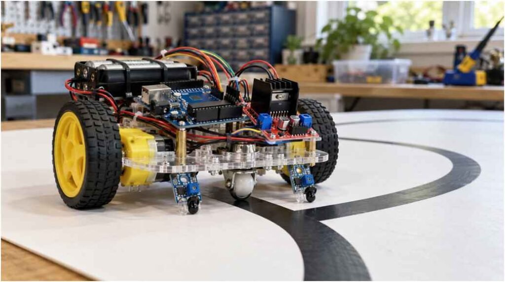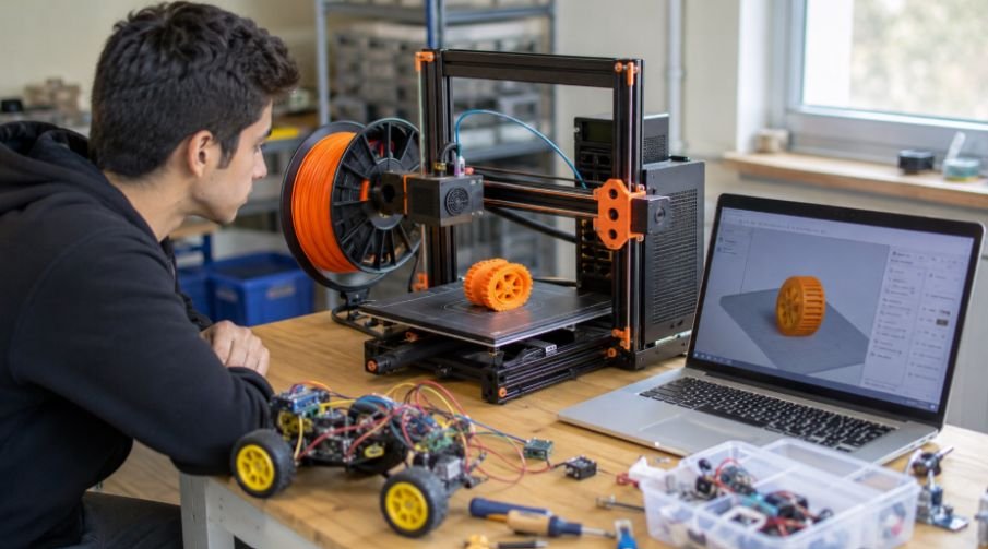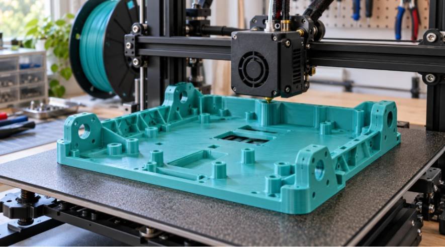
Most commercial acrylic robot chassis kits snap after a single high-speed wall collision. When you learn how to 3d print a robot chassis with arduino, you gain full control over structural rigidity, component placement, and custom sensor brackets.
I abandoned brittle off-the-shelf plastic plates three years ago in favour of custom-printed frames. A home 3D printer lets you design integrated standoffs, custom battery compartments, and reinforced motor mounts tailored to your exact payload.
Building your own platform requires balancing mechanical slicer settings with electrical isolation so your motors do not shake the microcontroller to pieces.
Sourcing Files and Dialing In Slicer Tolerances
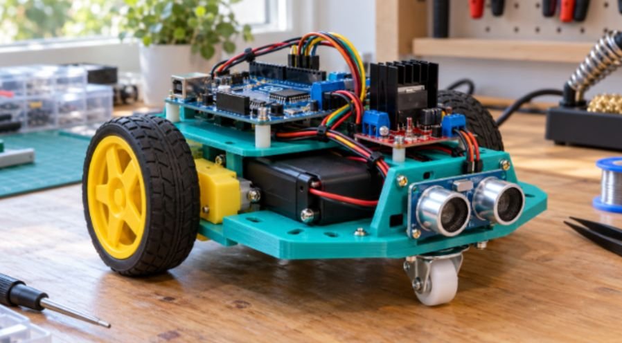
You do not need to model a platform from scratch on day one. Repositories like Printables host proven open-source geometries like the modular SMARS system and standard two-wheel-drive platforms. When I evaluate an STL file, I check the mounting hole spacing first.
The Arduino Uno requires four M3 mounting holes spaced exactly 53.3 mm by 48.3 mm apart. If you want to design a bespoke shape, tools like Autodesk Fusion allow you to sketch parametric baseplates around standard board dimensions.
Dimensional accuracy dictates whether your build succeeds or ends in stripped plastic. 3D printer extrusion expands slightly on interior perimeters. I always model horizontal bolt holes with a +0.3 mm clearance diameter. An M3 screw measures 3.0 mm, so an unthreaded pass-through hole must measure 3.3 mm in your CAD model. If you intend to tap threads directly into the plastic, size the hole to 2.8 mm.
+————————————————————–+
| MECHANICAL CLEARANCE TOLERANCES (M3) |
| |
| Standard Bolt Diameter: 3.0 mm |
| CAD Clearance Pass-Through: 3.3 mm (+0.3 mm thermal draft)|
| Direct Plastic Thread Tap: 2.8 mm (-0.2 mm bite depth) |
| Heat-Set Brass Insert Hole: 4.0 mm (tapered draft angle) |
+————————————————————–+
Best Filament Types for Motor Vibration
Material selection directly affects how your chassis handles torque and drops. Standard Polylactic Acid (PLA) offers high tensile strength and prints without warping on an unheated bed. Its rigidity prevents the baseplate from bending under heavy battery loads.
However, PLA is brittle. If you build a high-speed rover, impacts can shatter the front caster mount. Polyethylene Terephthalate Glycol (PETG) provides better impact resistance and flexural endurance. As noted in the Prusa Research Material Guide, PETG flexes under shock loads rather than snapping cleanly along layer lines.
I prefer PETG for outdoor rovers, though PLA remains completely adequate for smooth indoor floors. Avoid Acrylonitrile Butadiene Styrene (ABS) for basic chassis frames; the minor thermal benefit does not justify the warp risk across wide, flat geometries.
Essential Wall Thickness and Infill Ratios
A standard 15% decorative infill will fail under motor torque. The sheer stress created by standard yellow TT gearboxes twists weak motor brackets over time.
Set your slicer to at least 4 vertical perimeters and 4 top and bottom solid layers. Screws press against these outer shells; thin walls collapse when you tighten mounting nuts. For internal infill, choose a 25% Gyroid or Cubic pattern. Gyroid infill provides uniform, non-directional mechanical resistance, which absorbs vibration from DC gear motors far better than simple grid infill.
For builders looking to move beyond wheeled platforms, the same principles of structural strength, component positioning, and reliable fabrication also apply to multi-legged robots. This DIY hexapod spider robot guide provides inspiration for exploring more complex robotic designs that require carefully engineered frames and coordinated movement mechanisms.
Print at a 0.2 mm layer height. A 0.28 mm draft profile prints faster, but layer adhesion drops significantly, leaving your motor mounts vulnerable to delamination along horizontal seams.
Hardware and Component Assembly
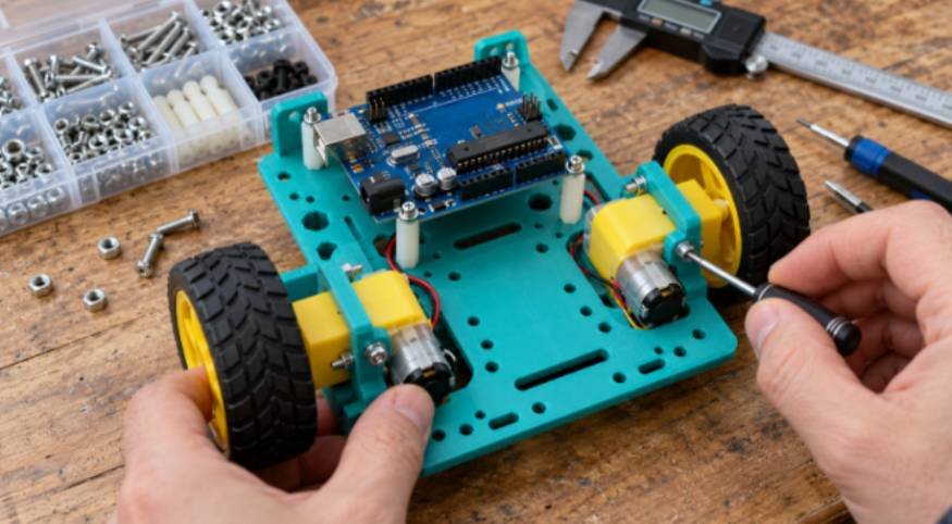
Once the print finishes, let the build plate cool completely. Prying a thin chassis plate off a warm print bed introduces permanent structural warps that prevent all four wheels from contacting the floor evenly.
Inspect all M3 holes with an engineer’s deburring tool or a 3 mm drill bit turned by hand to remove stray strings.
[ FRONT CASTER WHEEL ]
|
+—————–+
| HC-SR04 SENSOR |
+—————–+
|
+—————–+
| ARDUINO UNO | <— 3mm Air Gap via Standoffs
+—————–+
|
+—————–+
| L298N DRIVER | <— Direct frame-mount heatsink
+—————–+
|
[TT MOTOR] [TT MOTOR]
(Left) (Right)
Securing TT Gear Motors Without Cracking Struts
Standard yellow TT motors feature two pass-through mounting slots. You need M3x30 mm bolts to secure these motors to 3D printed mounting tabs.
Never overtighten these screws. Hand-tighten them until the locknut meets the plastic bracket, then apply a half-turn with a hex key. Excessive clamping pressure crushes the small internal alignment ribs on the motor’s plastic gearbox shell. If your design utilizes snap-fit retention clips, warm the plastic tabs gently with a hairdryer before pushing the motors in.
This softens the polymer enough to prevent snap-off failures during initial insertion. Press-fit rubber-tread wheels onto the dual-flat output shafts only after the motor body is securely fastened to the chassis.
Mounting the Arduino Uno and L298N Driver
Never bolt an Arduino Uno directly flush against a flat plastic baseplate. Solder pins protruding from the underside of the PCB can wear through plastic burrs or bridge against stray hardware.
Print 3 mm raised standoffs directly into your chassis model, or use nylon washers beneath the board. Fasten the board using 6 mm M3 pan-head screws. If your print includes heat-set brass inserts, press them into the pilot holes using a soldering iron set to 220°C.
Mount your L298N motor driver nearby to keep motor lead wire lengths under 10 cm. Longer power leads introduce electromagnetic interference that disrupts logic pins. Ensure the metal heatsink on the L298N has open space around it for natural convective cooling.
Wiring Power Rails and Avoiding Brownouts
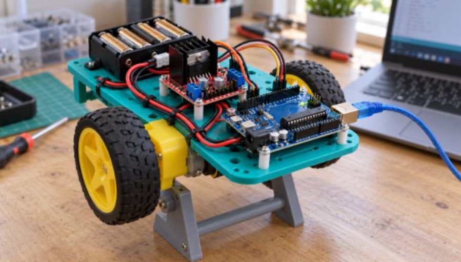
Motors demand sudden bursts of high current that logic boards cannot supply. Trying to power yellow TT gearboxes from the Arduino 5V pin forces an immediate processor reset known as a brownout.
Run two isolated power paths sharing a common ground. Use a 7.4V two-cell (2S) Li-ion pack or a 6-cell AA battery tray. Route the positive battery lead directly to the 12V input terminal of your L298N driver. Connect the battery ground to the L298N ground terminal.
Run a jumper wire from that same ground terminal directly to one of the Arduino GND pins. According to Arduino Documentation, maintaining a shared ground plane prevents digital control signals from floating between reference voltages.
Power the Arduino Uno separately through its barrel jack using a 9V clip, or run a 5V regulated feed from the motor driver into the board’s 5V pin if your driver board includes a clean built-in buck converter.
| Source Pin | Target Pin | Wire Type | Purpose |
| Battery (+) | L298N 12V / VCC | 20 AWG Hookup | High-current motor supply rail |
| Battery (-) | L298N GND | 20 AWG Hookup | High-current power return |
| L298N GND | Arduino GND | 22 AWG Jumper | Shared digital ground reference |
| Arduino D5 | L298N ENA | 24 AWG Jumper | Left motor PWM speed modulation |
| Arduino D6 | L298N ENB | 24 AWG Jumper | Right motor PWM speed modulation |
| Arduino D8, D7 | L298N IN1, IN2 | 24 AWG Jumper | Left motor directional logic H-Bridge |
| Arduino D4, D2 | L298N IN3, IN4 | 24 AWG Jumper | Right motor directional logic H-Bridge |
Testing Firmware and Motion Logic
Before loading autonomous scripts, flash a basic directional check to confirm that motor leads are wired with correct polarity.
Upload a sketch that sets digital pins 7, 8, 4, and 2 as outputs. Send HIGH to pin 8 and LOW to pin 7 to turn the left motor forward. If the left wheel spins in reverse, do not alter your code. Simply switch off the battery pack and swap the physical positions of the two motor wires inside the screw terminals on the driver board. Correcting polarity at the hardware layer ensures consistent behavior across future software updates.
After validating the drivetrain and confirming reliable motor control, you can explore more advanced robotic platforms that build on the same principles of custom fabrication and embedded control.
Once your basic drivetrain functions smoothly, integrate navigation systems.
You can expand this baseplate into an Obstacle avoiding robot by mounting an ultrasonic sensor bracket to the front bumper.
If you prefer high-precision kinetic projects, adapt this modular printing approach to configure an inverted-pendulum Self-balancing robot using an onboard accelerometer shield.
Frequently Asked Questions
1. Which 3D printer filament is best for a robot chassis?
PETG offers the best durability against motor vibrations and impacts, while PLA works fine for smooth indoor testing.
2. Can an Arduino Uno supply power directly to DC drive motors?
No, DC motors draw excessive current that triggers continuous microcontroller brownout resets or burns out onboard voltage regulators.
3. How thick should a 3D printed robot chassis baseplate be?
A flat baseplate should measure at least 3 mm to 4 mm thick with 4 solid perimeter walls to resist motor twisting.
4. Why do my robot motors twitch instead of driving forward cleanly?
Motors twitch when the motor driver and Arduino do not share a common electrical ground wire, leaving logic reference voltages floating.
Stop Calibrating, Start Driving
3D printing frees you from the rigid constraints of commercial chassis kits. Once your slicer profile accounts for thermal expansion and mechanical vibration, assembling a durable robotic frame becomes a repeatable, afternoon task. Grab your digital calipers, measure your battery tray dimensions, and push your first prototype plate to the printer.