I built my first outdoor robotic vehicle three years ago, and it stalled on my lawn within fifteen seconds. Ground drive systems demand real torque, clean current, and reliable localization that standard indoor kits simply cannot deliver.
Tackling an autonomous rover project DIY requires bridging basic microcontroller code with real-world physics. If you want a ground vehicle that reaches outdoor waypoints without human intervention, you must design around sensor limitations, battery voltage drops, and magnetic interference from your own drive motors.
[ 7.4V Li-ion Battery Pack ]
│ │
▼ ▼
[ Buck Converter ] [ L298N Driver ]
│ │
(Stable 5V) (High Current)
│ │
▼ ▼
[ Microcontroller ] [ DC Motors ]
Core Architecture: Hardware That Survives the Field
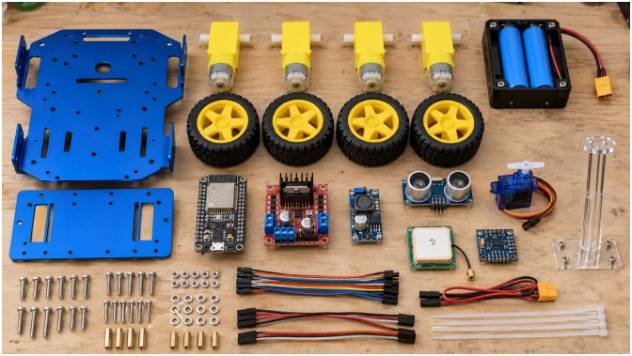
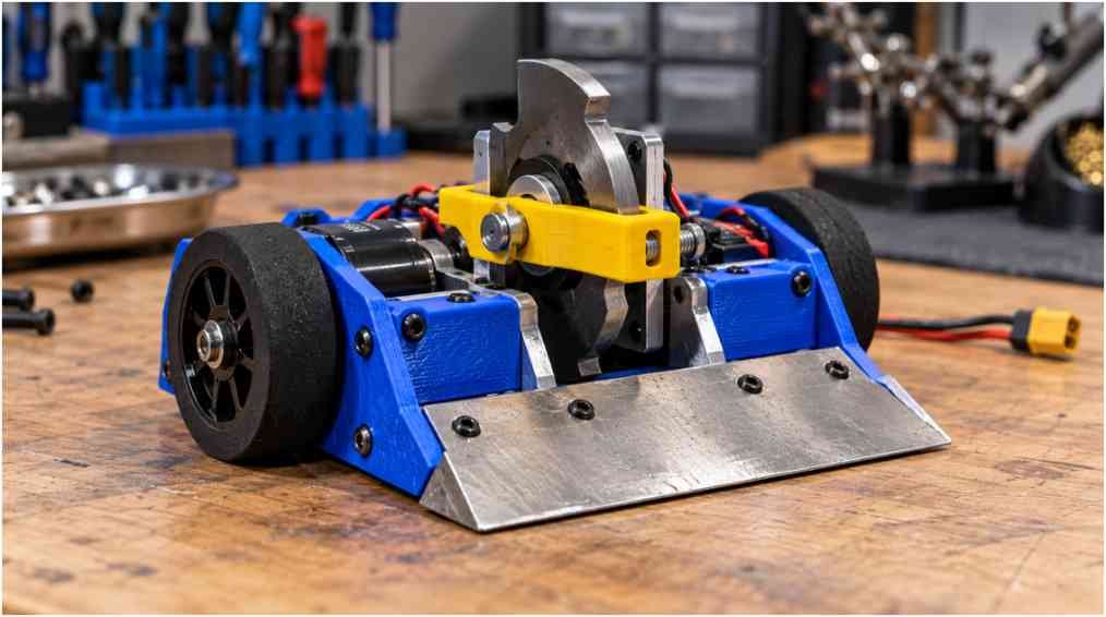
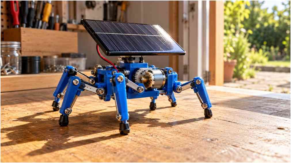
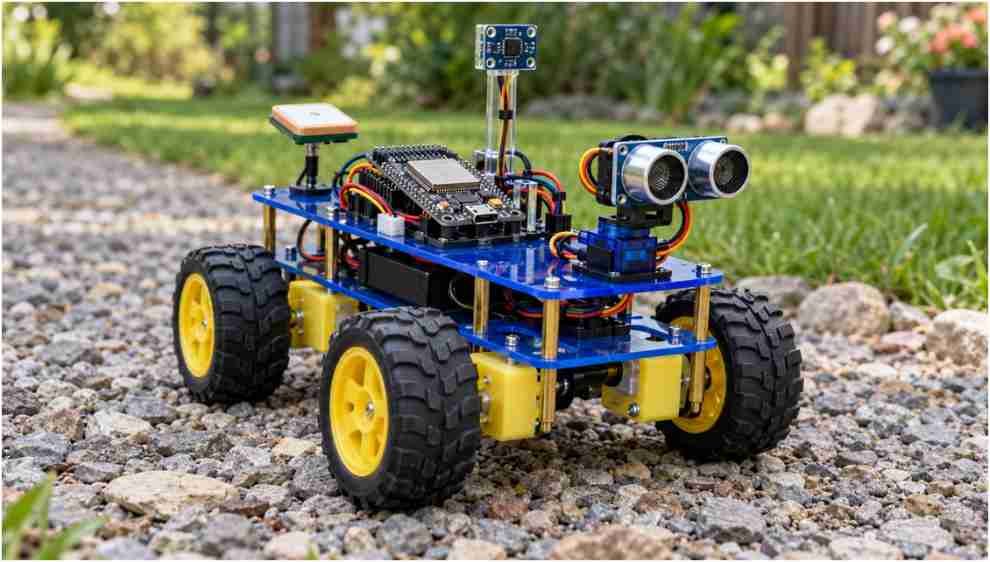
A successful autonomous ground bot relies on balanced electrical design rather than expensive processors. I chose a 4WD differential-drive chassis featuring four geared yellow DC motors paired with an ESP32 microcontroller board. The dual-core processor on the ESP32 lets you isolate sensor parsing on core 0 while executing motor PWM routines on core 1.
Motor Control and Power Distribution Realities
Most beginner rover builds share a fatal design flaw: feeding microcontroller logic directly from the motor driver’s internal linear regulator. Brushed DC motors inject massive inductive spikes back into the power rail. The classic Texas Instruments application reports on H-bridge drivers outline how inductive flyback degrades system stability.
I run two 18650 Li-ion cells in series to provide a 7.4V nominal bus to the L298N motor driver. Instead of using the driver’s 5V breakout to power the logic board, I route the raw battery output through a separate step-down buck converter tuned strictly to 5.0V. Adding a 470 µF decoupling capacitor across the ESP32 power pins eliminates the low-voltage micro-resets that occur during hard pivot turns.
Sensor Fusion: Ultrasonic Ranging vs. Environmental Noise
For close-range object detection, a front-facing HC-SR04 ultrasonic sensor mounted on an SG90 micro servo provides dependable perimeter scans. Outdoor environments present soft grasses and angled curbs that disperse high-frequency 40 kHz audio pulses. When the acoustic pulse bounces away from an obstacle rather than returning to the receiver, the sensor reports an open channel.
I program the rover to use an Obstacle avoiding sweep routine: it halts, rotates the servo 45 degrees left and right, and takes the median of three sequential pings. Discarding single-sample outliers prevents the rover from steering erratically around wind gusts and ground clutter.
Front
0°
\ /
-45° \ / +45°
Left \ / Right
[R] Rover
Wiring the System Without Brownout Failures
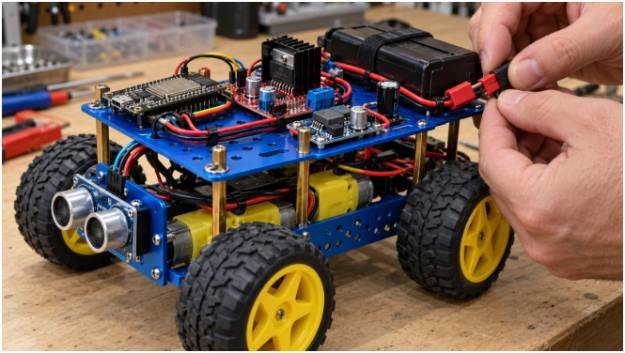
Wiring mistakes destroy more robotic components than programming errors. Establishing a solid common ground between your motor driver, battery ground, and computing module ensures your logic levels remain intact.
+——————–+ +———————+
| 7.4V Li-ion Pack |=======>| L298N Driver VMS |
+——————–+ +———————+
│ │
▼ ▼
+——————–+ +———————+
| DC-DC Step-Down 5V |=======>| ESP32 / Arduino 5V |
+——————–+ +———————+
│ │
(Common GND) ───────────────── (Common GND)
The table below details the pin connections required to run the dual-bus power layout safely.
| Module Pin | Host Connection | Voltage Level | Primary Purpose |
| L298N OUT1 – OUT4 | DC Motor Terminals | 7.4V Switched | Left/Right track drive power |
| L298N IN1 – IN4 | ESP32 GPIOs 18, 19, 22, 23 | 3.3V Logic | Directional H-Bridge switches |
| L298N ENA / ENB | ESP32 GPIOs 25, 26 | 3.3V PWM | Motor speed modulation |
| HC-SR04 Trig | ESP32 GPIO 5 | 3.3V Logic | 10 µs trigger pulse output |
| HC-SR04 Echo | 1kΩ / 2kΩ Divider to GPIO 4 | 5V stepped to 3.3V | Echo duration measurement |
| Servo Signal | ESP32 GPIO 13 | 3.3V PWM | 180-degree sweep control |
| NEO-6M GPS TX | ESP32 GPIO 16 (RX2) | 3.3V Serial | NMEA sentence streaming |
| QMC5883L SDA/SCL | ESP32 GPIO 21 / 22 | 3.3V I2C | Heading vector polling |
The Navigation Stack: Integrating GPS and Compass Heading
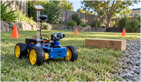
Once basic wall detection functions reliably, autonomous navigation requires knowing where you are and which way you point. You cannot build a functional path planner using GPS coordinates alone. Standard civil GPS receivers update between 1 Hz and 5 Hz, providing accurate ground coordinates but completely failing to determine vehicle orientation while stationary.
True North
▲
│ θ = Target Bearing
│ /
│ /
│/
[Rover] ════════════> Target Waypoint
\
\ α = Current Heading
▼
Eliminating Hard and Soft Iron Distortion
Attaching a magnetometer directly to a chassis plate ruins your heading calculations. Running motors generate dynamic electromagnetic fields, while chassis screws and battery casings create static magnetic distortions.
During my track tests, placing a QMC5883L sensor on the top chassis plate resulted in heading errors exceeding 40 degrees whenever the motors drew more than 800 mA. Elevating the compass 12 centimeters on a rigid acrylic mast slashed that deviation down to less than 3 degrees.
You also need to correct for local declination. True geographic North differs from magnetic North based on your exact global location. I fetch local magnetic declination angles directly from the National Oceanic and Atmospheric Administration calculator and inject that offset value into the onboard azimuth parser.
Solving the Cross-Track Steering Mathematics
The navigation loop runs on coordinate geometry. We read our current position from a NEO-6M GPS module parsed through the TinyGPS++ library on the Arduino Official Reference platform.
The distance between the rover’s current coordinates (1,1) and the target destination (2,2) is calculated using the haversine formula, where Earth’s radius R6,371,000meters:
a=22+(1)(2)22
$$d = 2R \cdot \operatorname{atan2}\left(\sqrt{a}, \sqrt{1-a}\right)$$
Calculating the target bearing angle demands spherical trigonometry:
$$\theta = \operatorname{atan2}\left(\sin(\Delta\lambda)\cos(\phi_2),\; \cos(\phi_1)\sin(\phi_2) – \sin(\phi_1)\cos(\phi_2)\cos(\Delta\lambda)\right)$$
With the target bearing established in degrees and current heading provided by the compass, the rover computes steering error:
Error=Bearing-Heading
The software bounds this error strictly between -180 and +180. If the error evaluates to -35, the rover applies a proportional left-turn pulse rather than rotating 325 clockwise. The logic resembles balancing inverted pendulums found in a [Self-balancing] robot chassis: small, continuous closed-loop updates yield straight trajectories.
Lessons Learned From Field Failures
My initial outdoor test ended with the rover driving full-speed into a concrete base. Analyzing the failure log showed the GPS lost its satellite lock beneath an awning, causing the positioning algorithm to report coordinate (0.0000,0.0000).
The vehicle attempted to calculate a heading vector toward the Atlantic Ocean off the coast of Africa. To safeguard your hardware, design defensive code based on open-source ground vehicle principles seen in the NASA JPL Open Source Rover project:
- Enforce Dilution of Precision Limits: Never update motor headings if Horizontal Dilution of Precision (HDOP) exceeds 2.5 or if satellite count drops below six.
- Implement an Acceptance Radius: Civil GPS exhibits random drift of 1.5 to 3 meters. Attempting to hit an exact coordinate point causes the rover to circle endlessly. Set an arrival boundary radius of 2.5 meters.
- Set Up a Hardware Timeout: If the serial GPS buffer stops feeding valid sentences for more than 1,000 milliseconds, stop both motor banks instantly.
Frequently Asked Questions
1. What is the easiest microcontroller for a DIY autonomous rover?
The ESP32 is ideal because it offers integrated dual-core processing, hardware UART channels, and onboard Wi-Fi telemetry at low cost.
2. Why does my rover reset every time the motors start?
Inductive current surges from DC motors drop the system supply voltage, triggering brownout detector resets on your microcontroller board.
3. How accurate is GPS waypoint navigation on a small rover?
Standard civilian GPS modules achieve positioning accuracy between 1.5 and 3 meters under open skies.
4. Do I really need a compass module if my GPS reports heading?
Yes, because GPS heading estimates require steady forward motion, leaving stationary or pivoting rovers completely blind to their true orientation.
Deploy Your Chassis: Stop Bench Testing and Hit the Dirt
Bench testing with wheels spinning off the ground only confirms basic motor polarities. Real autonomous maturity happens when your rover encounters rough pavement, shifting grass friction, and real-world magnetic clutter. Connect your buck converter, elevate that compass mast, write conservative failsafes into your main loop, and test your first waypoint route in an open park.