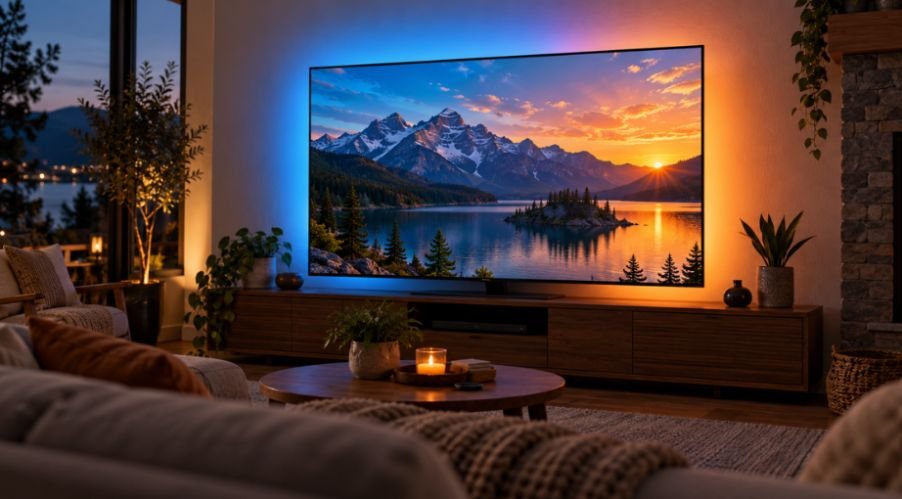
Want your TV’s colors to spill onto the wall without buying a replacement television? A DIY Ambient TV Backlight With Ws2812b And Raspberry Pi can do that, but reliable results depend on power, capture compatibility, and accurate color mapping.
My approach is to check those systems separately. I would start with solid LED colors, confirm the captured picture, and only then synchronize them. That sequence makes faults much easier to isolate.
Understand What This Setup Can Capture
The Raspberry Pi analyzes captured video and sends matching colors to addressable LEDs behind your screen.
For external HDMI sources, connect your streaming player or console to a splitter. One output feeds the TV; another feeds a USB capture card connected to the Pi.
A capture card with suitable HDMI passthrough can replace the separate splitter.
This arrangement cannot capture your TV’s built-in streaming apps. ARC and eARC return audio, not a usable copy of the screen.
Protected streaming content introduces another limitation. HDCP can block capture even when the television displays video normally. Verify compatibility with your actual source and service before buying.
Choose Your Raspberry Pi Ambilight Hardware
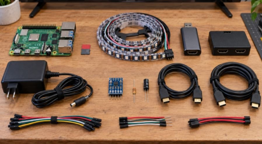
I would choose a Raspberry Pi 4 as a practical starting point. Add a microSD card, suitable Pi power supply, and network connection.
For the lighting, use a 5V WS2812B strip. Sixty LEDs per meter provides closely spaced pixels, although thirty reduces wiring demands and power consumption.
You also need a dedicated LED supply, HDMI capture hardware, cables, and suitable power-distribution connectors.
Include a 74AHCT125 logic-level shifter, a 330–470Ω data resistor, and a 500–1,000µF capacitor rated above 5V. Raspberry Pi GPIO signals are 3.3V; LED power is 5V. Adafruit’s NeoPixel guidance explains these signal-conditioning components.
Check passthrough specifications carefully. “4K input” does not guarantee 4K HDR output, 120Hz, or variable refresh rate.
Calculate WS2812B Power Before Buying
Here is a worked example rather than a blanket “buy 10 amps” recommendation.
Suppose your measured mounting path totals 3.6 meters. At 60 LEDs per meter, that gives 216 LEDs.
Using the conservative 60mA-per-pixel estimate:
216 × 0.06A = 12.96A, or approximately 65W at 5V.
Adding 20% planning headroom gives about 15.6A. A suitable 5V, 16A-or-higher supply would cover that assumed load. Actual strip specifications may differ.
The official Raspberry Pi ambient-lighting tutorial also uses this conservative current calculation.
My takeaway: calculate from the installed pixel count. Lower software brightness reduces normal consumption, but it does not replace correctly rated wiring and connectors.
Wire the WS2812B Strip Correctly
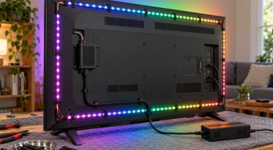
Disconnect power before assembling or changing connections.
For a compatible Pi 3 or Pi 4 PWM setup, wire GPIO18, physical pin 12, to the level shifter’s input. Connect its output through the data resistor to the strip’s DIN pad.
Power the 74AHCT125 from 5V, share its ground, and enable the selected channel according to its datasheet. Place the resistor near the first pixel.
Connect the LED supply’s positive output to the strip’s 5V input. Connect supply ground to strip ground and Pi ground, such as physical pin 6.
Place the capacitor across the strip’s power input, observing polarity.
I would power the Pi through its normal power connector. Do not route strip current through the Pi or connect separate supplies’ positive outputs together.
Mount the LEDs and Distribute Power
Measure the mounting path before cutting. Keep LEDs hidden from the front and clear of ventilation openings.
Follow the strip’s arrows: data must enter DIN and travel continuously around the television. Cut only at marked pads.
Count each edge and record the starting corner from a consistent viewing direction.
Long LED strips often need power at multiple points. Run appropriately sized, fused branches from the same supply to prevent voltage drop. For another electronics project involving specialized hardware selection, explore this comparison of Micro Swiss vs E3D V6 for printing carbon fiber filament.
Avoid carrying substantial strip current through thin jumper wires or underrated barrel connectors.
Choose Hyperion or HyperHDR
Hyperion is a capable ambient-lighting platform with broad controller support. HyperHDR is a related project with an explicit focus on HDR processing and capture calibration.
I would choose HyperHDR when HDR content is central to the build. For SDR, either can work with a compatible capture and LED-output arrangement.
HyperHDR provides LUT calibration and automatic tone-mapping features. A lookup table transforms captured color values efficiently, helping map HDR-derived input into colors suitable for the LEDs.
However, software cannot reconstruct information already clipped or incorrectly converted upstream. HyperHDR documents Dolby Vision support specifically for compatible low-latency Dolby Vision, or LLDV, hardware chains. Universal Dolby Vision compatibility would be an overpromise.
Use the HyperHDR project documentation to select a supported release and installation method.
Install and Configure Your Ambient Lighting
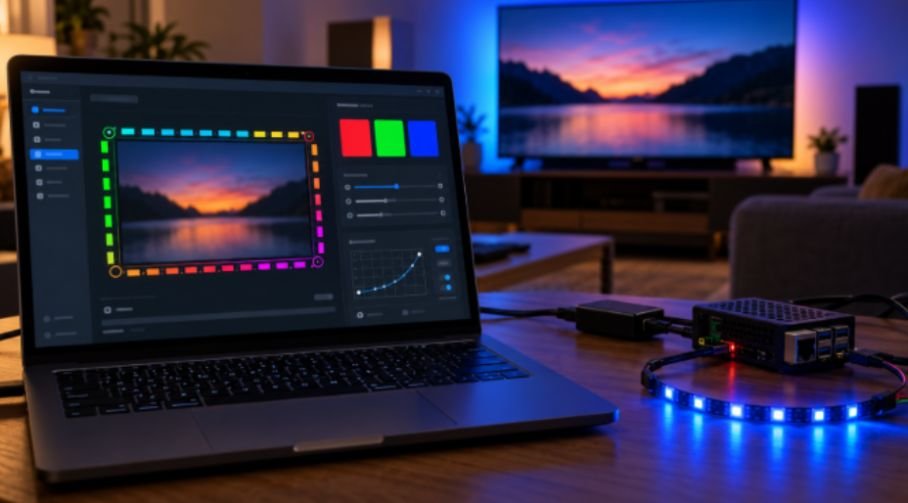
Flash a current image supported by your selected Pi and software. HyperBian provides Hyperion preinstalled; HyperHDR offers its own installation options.
Configure networking and SSH where the image supports them. Then boot the Pi and open http://<pi-ip-address>:8090.
For traditional Hyperion PWM output, select ws281x, enter the pixel count, and choose GPIO18. Follow the documented service permissions; PWM requires root access.
Pi 5 needs a different approach. Current HyperHDR documentation describes an RP1/PIO method requiring a matching overlay and LED count. Follow that model-specific procedure rather than copying older PWM settings.
Map the LEDs Before Enabling HDMI Capture
Enter the top, bottom, left, and right pixel counts. Set the first LED position and strip direction.
Test solid red, green, and blue. If colors swap, adjust byte order; GRB is common but not universal.
Next, run a moving pattern. Confirm that its physical direction matches the layout preview.
I would complete these checks before involving HDMI. A correct solid-color test separates LED faults from capture problems.
Configure USB Capture and HDR Tone Mapping
Select the USB grabber and inspect its live preview. Start with a modest supported capture resolution, such as 720p at 30fps.
The Pi samples screen regions; it does not need a full-resolution copy of every television pixel.
Confirm aspect ratio, crop unwanted borders, and enable black-bar detection if available. A downscaler reduces resolution; it does not necessarily perform HDR-to-SDR tone mapping.
For HDR, calibrate the capture chain using HyperHDR’s supported process. Check both SDR and HDR afterward to avoid applying the wrong correction.
Troubleshoot Without Chasing Your Tail
Random flashes suggest checking common ground, level shifting, loose connections, and data-wire length first.
A strip that turns pink or dims toward its far end suggests voltage drop. Measure voltage under load before adding power injection.
Correct colors on the wrong screen edge indicate a layout, direction, or starting-offset problem.
A black capture preview points toward the source, HDMI negotiation, capture format, or content protection.
For sluggish lighting, reduce capture workload and excessive smoothing. Check CPU load before upgrading hardware.
Give Movie Night Its Glow-Up
I would finish with moderate brightness and a familiar scene containing faces, shadows, and bright highlights. The backlight should extend the picture comfortably.
Save your configuration once everything works. Then explore home automation projects with raspberry pi for scene control and shutdown routines.
If ros2 on raspberry pi is another project on your list, keep its resource demands in mind before sharing the same board.
Frequently Asked Questions
1. Can I build this without an HDMI splitter?
Yes, a compatible capture card with HDMI passthrough can provide both TV output and USB capture.
2. Will this work with built-in Netflix apps?
This HDMI capture arrangement cannot access video generated inside your television.
3. Can a Raspberry Pi 5 control WS2812B LEDs?
Yes, with supported software and the correct Pi 5 output configuration; older PWM instructions are not interchangeable.
4. Does HyperHDR fix every washed-out HDR capture?
No; results depend on the captured signal, calibration, tone mapping, and compatible upstream hardware.