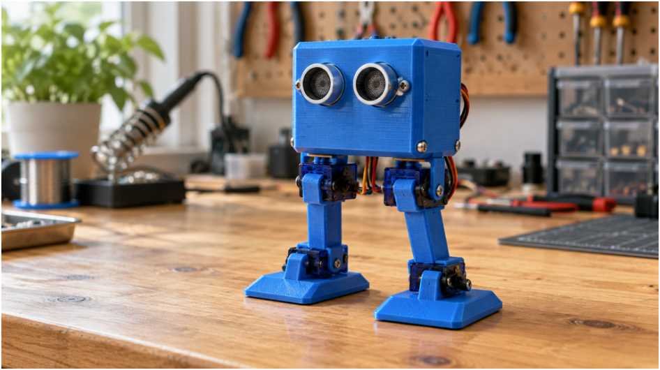
A robot that moves its legs but keeps falling needs more than faster code. For a DIY bipedal walking robot, I would start with four servos, a light frame, and careful calibration. The first goal is controlled weight transfer, followed by repeatable steps.
My approach puts standing, tilting, and power checks ahead of walking. That gives you a clear way to diagnose problems instead of changing several settings blindly.
Choose an Otto DIY Robot Build
An Otto-style design gives beginners a manageable starting point. Its four joints avoid the extra mechanics and programming of knees.
The Otto DIY Academy provides assembly resources and directs builders to printable body files. Choose matching instructions, electronics, and frame files from the same version.
For your first DIY bipedal walking robot, a complete kit can reduce sourcing mistakes. Check whether it includes printed parts, servo horns, screws, a power arrangement, and programming support.
If you already have a printer, sourcing parts separately allows more customization. Keep the original geometry initially; heavier heads and longer legs change how the robot balances.
Gather Arduino Biped Components
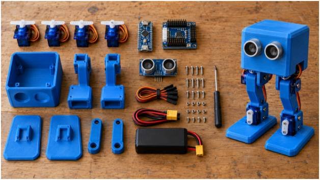
Match the Frame and Micro Servos
A basic DIY bipedal walking robot needs an Arduino Nano, compatible I/O shield, four micro servos, and a printed body. Add jumper wires, mounting screws, a switch, and a suitable power supply.
An HC-SR04 distance sensor and buzzer are optional additions. Walking itself does not require obstacle detection.
SG90 servos suit many lightweight designs. MG90S metal-geared alternatives need matching dimensions, mounting holes, and power specifications. I would check compatibility before treating either model as a direct replacement.
Print one servo pocket first. For your DIY bipedal walking robot, confirm the case fits without force before printing the remaining parts.
Give the Servos Reliable Power
Power deserves its own plan in a DIY bipedal walking robot. Four servos can demand substantial current during starts, reversals, or stalls.
Follow Arduino’s servo power guidance and use a suitable external servo supply. Connect its ground to the Arduino ground so control signals share a reference.
A regulated 5V rail may suit your chosen micro servos; verify their specifications. Size the supply using their combined current requirements, with headroom.
A single 18650 cell does not provide regulated 5V. It needs an appropriate boost converter, protection, and charger. A shield only solves this if its actual circuitry supports the required voltage and current.
Assemble and Calibrate Your Four-Servo Robot
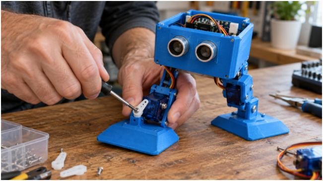
Center the Servos Before Assembly
Center every servo electronically before installing its horn. With Arduino’s Servo library, attach each servo to its signal pin and command 90 degrees.
Disconnect power before fastening the horns. Assemble the legs and feet in the neutral pose shown in your frame instructions.
For a DIY bipedal walking robot, commanded center and physical alignment are different things. Horn teeth rarely produce perfect alignment, so software trim may still be necessary.
Mount hip servos inside the body and ankle servos in their matching leg pieces. Route wires away from joints. Secure the battery near the center and prevent it from shifting during steps.
Connect the Arduino Nano Wiring
Use left hip on D2, right hip on D3, left foot on D4, and right foot on D5. Label left and right from the robot’s perspective.
Connect servo power wires to the suitable supply rail, grounds to common ground, and signal wires to those pins. Check your shield’s layout rather than assuming every connector follows the same order.
The official Otto Arduino library documents this mapping and provides home, walking, and turning functions.
Test each servo independently while supporting the body. For your DIY bipedal walking robot, record its direction when the command increases. Mirrored mounting can require opposite numerical directions.
Program a Stable Biped Walking Gait
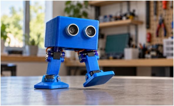
Understand the Four Walking Phases
A four-servo DIY bipedal walking robot uses lateral foot tilt and hip rotation to shuffle forward. On Otto-style geometry, the hip joints rotate around yaw axes; they do not act like knee-equipped human legs.
First, tilt toward the right support foot until the left foot clears the floor. Next, rotate the hips to advance the unloaded foot while the planted foot supports movement.
Then transfer weight onto the left foot. Finally, reverse the hip movement to advance the right foot.
The supplied reference uses ankle targets near 115 and 65 degrees, with hip targets near 120 and 60 degrees. These illustrate motion ranges, not universal settings.
I would begin with smaller offsets and increase them only after checking clearance. Both ankles receiving identical numbers does not guarantee the correct physical lean.
Smooth Each Movement
For a DIY bipedal walking robot, abrupt position commands can cause rocking and current spikes. Interpolate between poses over a timed interval.
A useful cosine easing profile is:
θ(t) = θstart + (θtarget − θstart) × [1 − cos(πt/T)] / 2
Here, T is the transition duration. This profile starts and ends with zero commanded velocity, reducing abrupt starts and stops.
Consider a calculated example: four 300ms transitions plus two 40ms settling pauses produce a 1,280ms cycle. A 90-to-115-degree move reaches 102.5 degrees halfway through its transition.
That is a planning example, not a measured performance claim. Servo speed, load, and surface grip determine actual movement.
Start with the library’s walking example before writing custom trajectories. Its timing parameter follows its own gait implementation; do not assume it equals one custom phase.
Fix Falls Before Adding Features
I would diagnose a DIY bipedal walking robot with a tilt-only test first. Disable hip movement and alternate gentle weight shifts.
Falling here points toward alignment, excessive lean, uneven feet, or poor weight distribution. Reliable tilting followed by failed walking suggests swing timing, foot drag, or grip problems.
If the controller resets when several servos move, check supply voltage under load and inspect connectors. Slowing the gait may mask weak power without fixing it.
Change one variable per trial. Record trim, tilt range, swing range, timing, surface, and successful cycles. This simple log makes improvements reproducible.
Once your DIY bipedal walking robot walks consistently, add distance sensing. Your Obstacle avoiding robot project can explain detection logic; check sensor readings between short walking actions.
Tiny Feet, Big Attitude: Take the Next Step
I would rather have ten controlled steps than one dramatic lunge. Give your DIY bipedal walking robot a repeatable starting pose and test it on a level floor.
Your next move is simple: center the servos, confirm both weight shifts, then attempt one slow walking cycle. For remote input, connect this build to your Gesture controlled robot project. Make lost communication return the robot to a stable standing pose.
Frequently Asked Questions
1. Can I build a DIY bipedal walking robot without a 3D printer?
Yes; choose a compatible kit with pre-made body parts or order prints from the matching design files.
2. How many servos does a beginner biped robot need?
An Otto-style biped uses four: two hip servos and two foot servos.
3. Why does my Arduino walking robot keep falling?
Check neutral alignment, weight placement, foot clearance, movement timing, and supply voltage under load.
4. Can a four-servo biped walk on carpet?
Carpet can catch the feet; begin on a flat, firm surface before testing other flooring.