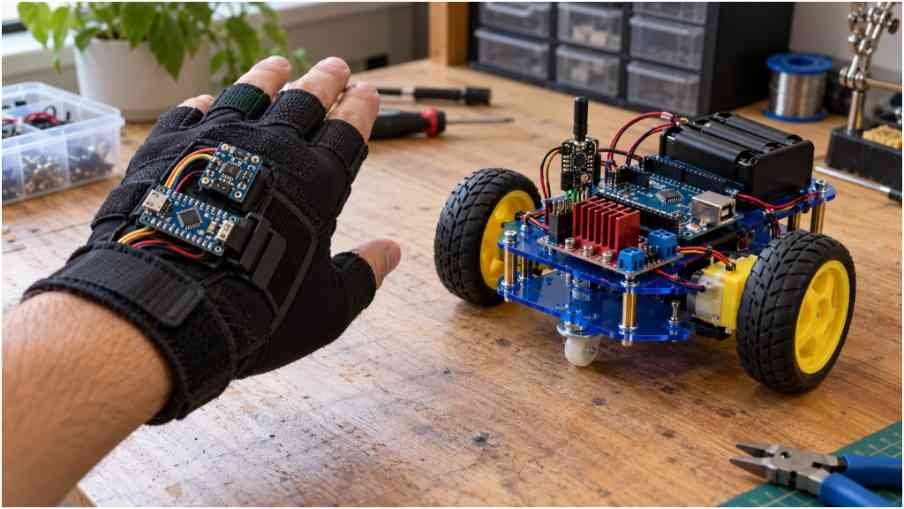
A wrist tilt should move your robot, and a flat hand should stop it. My approach to a Gesture controlled robot DIY project starts with making those two actions predictable.
I’d build a two-wheel Arduino car and a wearable transmitter, then test each system separately. That keeps a loose radio wire from looking like a programming problem. The plan below uses your Arduino, MPU6050, nRF24L01, and L298N setup, with practical corrections for power and calibration.
How the Wireless Hand-Controlled Robot Works
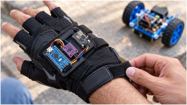
The glove reads hand orientation through an MPU6050 accelerometer and gyroscope. Its Arduino Nano converts tilt into forward, reverse, left, right, or stop commands.
An nRF24L01 radio sends those commands to another radio on the car. The receiver Arduino Uno controls the motor driver, which switches power to the motors.
For this Gesture controlled robot DIY build, tilt controls direction; finger movement does nothing. A hand-tracking robotic arm would need different mechanics and potentially more sensors.
Choose Parts That Work Together
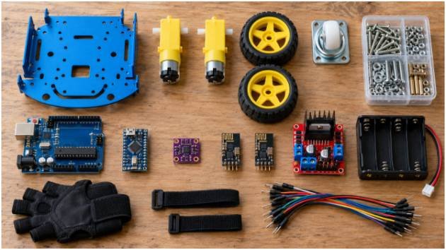
For Gesture controlled robot DIY hardware, start with a classic 5V Nano, Uno, MPU6050 breakout, two matching radios, L298N module, and two geared DC motors. Add a chassis, wheels, caster, switch, jumper wires, and secure mounts.
I’d choose two-wheel drive first. Four motors increase current demand, especially when turning or stalled. Check each motor’s stall current against the driver board’s realistic limits.
For a Gesture controlled robot DIY transmitter, a regulated USB supply is convenient during setup. A rectangular 9V battery can work through a suitable board input, but offers limited useful runtime.
For the car, use a protected battery pack matched to the motors, plus a regulated electronics supply. Two series lithium-ion cells reach 8.4V fully charged. Use a compatible charger, protection circuit, and enclosed holder.
Wire the Arduino Gesture Control Transmitter
Disconnect power before wiring. Mount the sensor firmly so its axes remain aligned with your hand.
Connect the MPU6050 Accelerometer
On the classic Nano, connect SDA to A4 and SCL to A5. Connect sensor ground to Nano ground. The official Arduino Nano pinout identifies these I2C connections.
Check your breakout before connecting power. The Adafruit MPU6050 breakout documentation specifies a regulator and level shifting that support 5V use. Generic boards may differ.
My Gesture controlled robot DIY wiring rule is simple: verify the breakout’s supply and logic requirements separately. The sensor chip’s limits and the breakout’s supported inputs are different specifications.
Connect Both nRF24L01 Radios
For each classic Nano or Uno, connect CE to D9, CSN to D10, MOSI to D11, MISO to D12, and SCK to D13. Connect GND to that unit’s common ground.
Use a stable 3.3V supply for the radio itself. Never feed 5V directly into its VCC pin. A regulator adapter may accept 5V upstream; check its markings.
Keep radio wires short. A local 10–100 µF capacitor across VCC and GND is a useful starting measure against supply dips. Observe capacitor polarity.
The radios belong to Nordic Semiconductor’s nRF24 family. Nordic now marks that family as unsuitable for new commercial designs, although existing hobby modules remain useful here.
Wire the Receiver and L298N Motor Driver
Connect the left motor to OUT1/OUT2 and the right motor to OUT3/OUT4. Wire IN1 to D2, IN2 to D3, IN3 to D4, and IN4 to D7.
For speed control, remove ENA and ENB jumpers, then connect ENA to D5 and ENB to D6. These PWM outputs avoid the radio’s assigned pins.
Connect battery positive to the module’s motor-supply terminal, often labeled “12V.” That label does not require a 12V battery. Join battery negative, driver ground, and receiver Arduino ground.
Check the module’s regulator-jumper instructions before using its 5V terminal. Don’t connect competing 5V supplies together.
The STMicroelectronics L298 datasheet describes separate logic and motor supplies. Its bridge also loses voltage under load, reducing what reaches your motors.
A Gesture controlled robot DIY car that barely moves may have a power problem. Increasing software speed cannot recover voltage lost through an overloaded supply or driver.
Program Hand Gestures Without Random Thresholds
Install RF24 and MPU6050_light through Arduino IDE’s Library Manager. Select the correct board and port before uploading separate transmitter and receiver sketches.
These instructions define the firmware behavior; complete sketches must implement the chosen library APIs and pin assignments.
Calibrate Neutral and Add a Deadband
Keep the glove stationary during sensor offset calibration. Then record the comfortable neutral pose and subtract its pitch and roll from subsequent readings.
For my Gesture controlled robot DIY control scheme, I’d begin with a 12-degree activation threshold. Return to stop below 8 degrees. This gap, called hysteresis, reduces command chatter.
Those angles are starting settings, not measured results. Confirm axis signs in Serial Monitor: sensor mounting can reverse forward and backward.
When both axes exceed the threshold, use the larger absolute tilt. Within the neutral region, send stop. This avoids accidental diagonal commands and arbitrary if-else priority.
Send Commands and Stop on Signal Loss
Send a small fixed-size packet every 20–50 milliseconds, including during neutral. Both sketches must match packet layout, radio address, channel, and data rate.
The receiver should start stopped, validate incoming commands, and track its last valid packet time. Disable both motor enables if no valid packet arrives for 250 milliseconds.
Consider this Gesture controlled robot DIY example: at 0.4 meters per second, a 250-millisecond timeout allows approximately 0.10 meters of travel before disabling drive. Coasting adds distance.
That calculation explains why I’d begin slowly. A radio timeout is a fallback; keep a physical power switch accessible.
Test Before the Wheels Touch Down
During Gesture controlled robot DIY testing, first print tilt readings and commands with motors disconnected. Next, confirm that the receiver prints the same commands.
Raise the wheels and test one motor at low PWM. If forward runs backward, correct its wiring or direction mapping. Then test both sides and neutral.
For the final Gesture controlled robot DIY check, switch off the transmitter while the wheels spin. Verify timeout stopping before floor testing.
If resets happen only when motors start, investigate battery sag, grounding, and electrical noise. If steering jitters while stationary, inspect mounting and calibration.
After reliable manual control, a Wall-following maze project offers a useful next step into autonomous sensing.
Your Hand Is the Boss—Make Stop Its First Command
I’d call a Gesture controlled robot DIY project ready only after neutral and signal-loss tests pass consistently. Secure the wiring, start at walking pace or slower, and increase speed gradually. Fancy steering can wait; predictable stopping earns the first victory lap.
FAQs
1. Can I build a gesture-controlled robot with Arduino Nano?
Yes; two classic Nanos can handle the transmitter and receiver when wiring and power requirements match.
2. Why does my MPU6050 robot move with a flat hand?
Recalibrate the neutral pose, secure the sensor, and widen the deadband to reject small movements.
3. Can a gesture-controlled robot work without Bluetooth?
Yes; paired nRF24L01 modules provide the wireless link used in this build.
4. What makes a Gesture controlled robot DIY car stop when disconnected?
A receiver timeout disables motor drive when valid packets stop arriving.