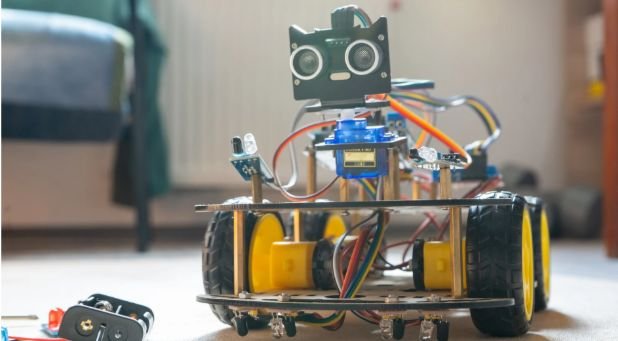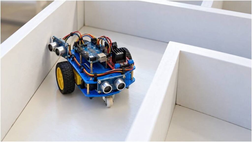
Most maze-solving robots fail at their first corner because builders treat wall following as a simple binary switch. When I assembled my first autonomous chassis, I learned the hard way that basic threshold logic makes a platform oscillate violently until it crashes into a corner. A reliable wall-following maze robot requires clean sensor physics, solid differential drive geometry, and a tuned feedback loop.
[Left Wall]
| ^
d_target | |
v |
+—+—+—+
| [L] [F] | —> Forward Heading
| Robot |
| Body |
+——-[R]-+
The Physics and Mechanics Behind Wall Traversal
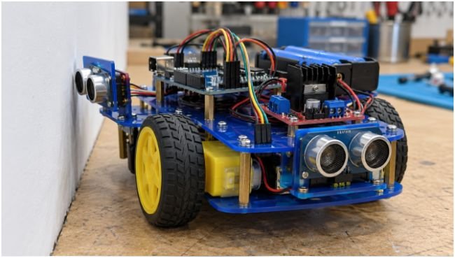
Navigating an unknown environment without pre-mapped coordinates requires reliable local feedback. The robot must establish a reference plane using solid obstacles and adjust its heading dynamically.
+———————————————————————–+
| SENSING & DIFFERENTIAL CONTROL PIPELINE |
+———————————————————————–+
| [Left / Front Ultrasonic Sensors] |
| | (Raw Echo Timings, 25ms Timeout) |
| v |
| [Noise Rejector & Median Filter] |
| | (Discards Glancing-Angle Reflections) |
| v |
| [PID Feedback Controller] ——> e(t) = Target_Distance – Left_Dist |
| | u(t) = Kp*e + Ki*∫e + Kd*(de/dt) |
| v |
| [Differential Drive Allocation] |
| | Motor_Left = Base_PWM + u(t) |
| | Motor_Right = Base_PWM – u(t) |
| v |
| [L298N / L293D H-Bridge Driver] |
+———————————————————————–+
Selecting Sensors Beyond Standard Sonar Cones
Ultrasonic sensors like the HC-SR04 send a 40 kHz acoustic burst that disperses in a roughly 15-degree cone. When the robot turns parallel to a wall, sound waves reflect away at glancing angles rather than returning to the receiver. This acoustic phenomenon, documented extensively in ultrasonic research published via IEEE Xplore, causes the sensor to read an artificial infinite distance.
Mounting side sensors at a forward rake of approximately 10 to 15 degrees helps catch reflections early while the robot rolls forward. Pair your sonar units with sharp infrared triangulation sensors for close-range detection to eliminate acoustic dead zones under four centimetres.
Differential Drive Geometry and Pivot Radii
A two-wheel differential drive platform with a rear passive caster yields a zero-radius turn capability. Place your sensors directly along the axis of rotation. Placing a distance sensor too far ahead of the drive wheels introduces an artificial lead error: every turn swings the sensor through a wide arc, confusing your distance algorithm.
Keep your track width—the distance between drive wheel contact patches—calibrated to your maze’s corridor width. Mazes formatted to standard specifications outlined by the National Institute of Standards and Technology (NIST) require vehicles to maintain at least 30 mm of clearance on either side to allow for continuous course corrections without scraping boundaries.
Implementing Reactive Navigation vs Closed-Loop PID
Discrete logic relies on fixed if-else statements: if the left sensor reads more than fifteen centimetres, turn hard left. This bang-bang approach creates a zig-zag trajectory that bleeds kinetic energy and risks tipping lightweight platforms.
Discrete / Bang-Bang Trajectory:
[Wall] ————————————————————-
\ /\ /\ /\ / (Erratic Ping-Pong Motion)
\ / \ / \ / \ /
\–/ \–/ \–/ \–/
Continuous Closed-Loop PID Trajectory:
[Wall] ————————————————————-
~~~~~~~~~~~~~~~~~~~~~~~~~~~~~~~~ (Smooth Parallel Line)
The Left-Hand Rule and the Island Maze Trap
The Left-Hand Rule dictates four sequential priorities:
- Turn left if the path opens.
- Advance straight if the left wall remains present and the front is clear.
- Turn right if blocked ahead and on the left.
- Rotate 180 degrees at a dead end.
This priority stack solves any simply connected maze where walls run continuously to the exterior boundary. If the exit sits on an isolated central island, a left-hand follower circles that interior structure endlessly. Solving multiply connected labyrinths ultimately requires mapping frameworks such as the Flood Fill algorithm or Tremaux’s method.
Developing Continuous Closed-Loop Steering
A Proportional-Integral-Derivative (PID) controller corrects your heading smoothly. Instead of making hard turns, it continuously adjusts the power delivered to each wheel.
The error term measures your deviation from the target wall spacing:
e(t)=dtarget–dactual
+—————+————————————-+—————————————+
| Term | Mathematical Action | Practical Effect on Maze Platform |
+—————+————————————-+—————————————+
| Proportional | Kp * e(t) | Primary steering torque back to line |
| Integral | Ki * ∫ e(t) dt | Corrects mechanical pull & wheel slip |
| Derivative | Kd * (de(t) / dt) | Counter-steers to stop overshooting |
+—————+————————————-+—————————————+
Full Hardware Schematics and Pin Architecture
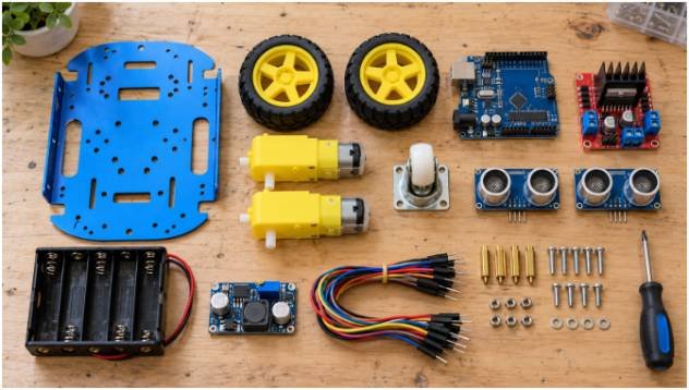
This layout links an ATmega328P microcontroller via standard connections documented on the Arduino Documentation platform, routing control through an L298N dual H-bridge motor driver.
+————————————————————-+
| ARDUINO UNO R3 |
| |
| [D5~] [D6~] [D7] [D8] [D11] [D12] [D9] [D10] |
+—-+—–+——-+——+——+——+——-+——-+—–+
| | | | | | | |
| | | | | | | |
v v v v v v | |
[ENA] [ENB] [IN1] [IN2] [IN3] [IN4] | |
+——————————————+ | |
| L298N DUAL H-BRIDGE | | |
+——————————————+ | |
| | | | | |
v v v v v v
[Left Motor] [Right Motor] [Trig] [Echo]
+—————–+
| HC-SR04 SENSOR |
+—————–+
Power the logic and drive stages from separate power rails. Connecting digital pins and high-draw DC gearmotors to the same unregulated battery line causes brownouts whenever motors stall or reverse direction. Feed 7.4V or 11.1V lithium-polymer power directly into the motor driver VIN terminal, while feeding the Arduino through its onboard regulator via VIN or a dedicated 5V buck converter.
Production-Ready Arduino PID Control Script
This deployment script uses hardware timers and avoids delay() commands. It features sensor outlier rejection alongside anti-windup clamping on the integral accumulator.
C++
// Target wall parameters
const float TARGET_DIST = 10.0; // Desired distance in cm
const int BASE_SPEED = 150; // Base motor PWM (0-255)
const int MAX_SPEED = 220;
// Hardware pin mapping
const int PIN_TRIG = 9;
const int PIN_ECHO = 10;
const int PIN_ENA = 5; // PWM Left
const int PIN_IN1 = 7;
const int PIN_IN2 = 8;
const int PIN_ENB = 6; // PWM Right
const int PIN_IN3 = 11;
const int PIN_IN4 = 12;
// Closed-loop PID parameters
float Kp = 14.0;
float Ki = 0.04;
float Kd = 9.5;
// State variables
float integralValue = 0.0;
float lastError = 0.0;
unsigned long lastCompute = 0;
void setup() {
pinMode(PIN_TRIG, OUTPUT);
pinMode(PIN_ECHO, INPUT);
pinMode(PIN_ENA, OUTPUT);
pinMode(PIN_IN1, OUTPUT);
pinMode(PIN_IN2, OUTPUT);
pinMode(PIN_ENB, OUTPUT);
pinMode(PIN_IN3, OUTPUT);
pinMode(PIN_IN4, OUTPUT);
// Set directional pins forward
digitalWrite(PIN_IN1, HIGH);
digitalWrite(PIN_IN2, LOW);
digitalWrite(PIN_IN3, HIGH);
digitalWrite(PIN_IN4, LOW);
lastCompute = millis();
}
float measureDistanceCM() {
digitalWrite(PIN_TRIG, LOW);
delayMicroseconds(2);
digitalWrite(PIN_TRIG, HIGH);
delayMicroseconds(10);
digitalWrite(PIN_TRIG, LOW);
// 18ms timeout bounds reading range to ~3 meters
long duration = pulseIn(PIN_ECHO, HIGH, 18000);
if (duration == 0) return TARGET_DIST;
float calculated = (duration * 0.0343) / 2.0;
// Reject outlier spikes from acoustic scatter
if (calculated > 60.0) return TARGET_DIST;
return calculated;
}
void loop() {
unsigned long currentTime = millis();
float deltaTime = (currentTime – lastCompute) / 1000.0;
// Run the loop every 30 milliseconds
if (deltaTime >= 0.030) {
float currentDistance = measureDistanceCM();
float error = TARGET_DIST – currentDistance;
// Integral accumulation with anti-windup clamping
integralValue += (error * deltaTime);
integralValue = constrain(integralValue, -25.0, 25.0);
// Derivative calculation
float derivative = (error – lastError) / deltaTime;
// Generate output correction value
float controlSignal = (Kp * error) + (Ki * integralValue) + (Kd * derivative);
// Apply adjustments to differential motors
int leftDuty = constrain((int)(BASE_SPEED + controlSignal), 0, MAX_SPEED);
int rightDuty = constrain((int)(BASE_SPEED – controlSignal), 0, MAX_SPEED);
analogWrite(PIN_ENA, leftDuty);
analogWrite(PIN_ENB, rightDuty);
lastError = error;
lastCompute = currentTime;
}
}
Bench-Testing and Calibration Protocol
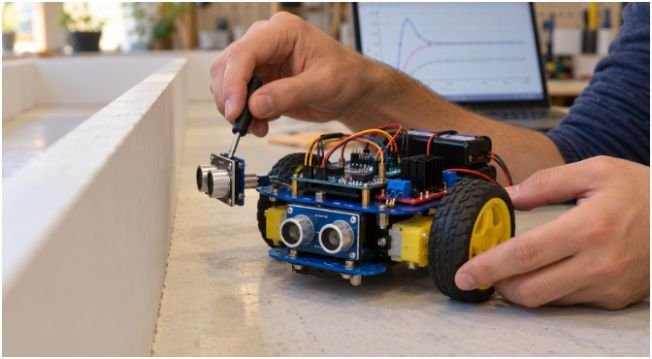
Tuning PID values on a live track requires a systematic approach. Place your platform on an elevated test stand first to ensure the drive wheels spin in the correct direction when the sensors detect obstacles.
- Set all gains to zero: Configure Kp=0, Ki=0, and Kd=0. Increase base PWM until the chassis moves forward without stalling or pulling.
- Dial in proportional gain (Kp): Increase Kp in steps of 2.0. The robot will begin steering toward the wall setpoint. Continue increasing Kp until the platform exhibits a continuous, steady side-to-side oscillation along straight stretches.
- Introduce derivative damping (Kd): Cut Kp by 30 percent, then raise Kd in steps of 1.0. Derivative action dampens oscillations by resisting rapid changes in error. You will observe the vehicle track parallel to the wall without weaving.
- Address steady-state offset (Ki): If the robot runs parallel to the wall but stays consistently two centimetres off target, introduce a tiny Ki value (0.01 to 0.05). This adds persistent micro-corrections over time to eliminate offset bias. Guidelines from engineering repositories on Society of Robots suggest keeping Ki as low as possible to prevent instability at high speeds.
Frequently Asked Questions About Maze Robots
1. Can a wall-following robot solve every maze configuration?
No, it fails inside multiply connected mazes with detached island loops containing the target exit.
2. Why does my ultrasonic robot crash into sharp inside corners?
Sound waves scatter away at acute angles, causing the sensor to misread an open corridor instead of a wall.
3. What is the ideal base PWM speed for small DC gearmotors?
Set base PWM between 120 and 160 on a standard 8-bit scale to ensure reliable starting torque without wheel slip.
4. How do I stop my robot from pulling toward one side during straight runs?
Apply an integral gain term or calibrate individual motor trims in your code to balance gearbox friction differences.
Escape the Grid: Next-Gen Autonomous Navigation
A calibrated PID loop turns an erratic wall-following maze robot into a reliable autonomous platform. Building an effective navigation system comes down to managing sensor latency, eliminating acoustic interference, and matching motor output to vehicle mass.
Solving a simply connected maze demands predictable, millimetre-accurate distance tracking. If you transition from building a basic obstacle avoiding robot continuous wall following forms the bedrock of autonomous ground vehicle engineering.
Run your tests on straight test tracks before attempting complex junctions, check your echo timeouts, and confirm your chassis balance holds true across every run. Once your vehicle tracks true along a single continuous surface, add front break-beam sensors to handle tight 90-degree outer corners and complex corridor intersections.
If you are scaling down high-torque drive mechanisms seen in a mini combat robot continuous wall following forms the bedrock of autonomous ground vehicle engineering.