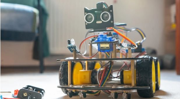
A robot can move perfectly and still fail if it cannot sense what surrounds it. Understanding how robot sensors work shows how machines detect obstacles, judge force, maintain balance, and choose their next action.
I treat every sensor as a translator. It converts light, sound, pressure, heat, or motion into an electrical signal. The controller turns that signal into usable data. Software then decides how the robot should respond.
The Core Process Behind Robotic Sensing
The clearest explanation of how robot sensors work is the Sense–Think–Act cycle. The robot measures a condition, interprets the result, and responds through motors, grippers, lights, valves, or other actuators.
The Sensor Detects a Physical Change
The first step is transduction. A sensing element reacts to a physical event by changing voltage, resistance, capacitance, current, or another measurable property.
A strain gauge provides a clear example. Stretching or compressing it changes its electrical resistance. Signal-conditioning electronics turn that tiny change into a usable force reading. Analog Devices describes this process as converting mechanical deformation into an electrical signal.
The sensor does not identify the object by itself. It only reports a physical response.
Electronics Convert the Signal Into Data
Many sensors produce a continuously changing analog voltage. A microcontroller needs a numerical value, so an analog-to-digital converter, or ADC, samples that voltage.
Arduino documents that the classic UNO uses a 10-bit ADC. It represents an analog input with 1,024 possible levels, numbered from 0 to 1,023. With a 5-volt reference, each step represents approximately 4.9 millivolts.
Digital sensors perform part of this conversion internally. They send measurements through interfaces such as I2C, SPI, or UART. The controller must still apply the correct unit, scale, and calibration value.
Software Turns Data Into Action
Raw readings rarely control a robot directly. Software may average several samples, reject extreme values, apply calibration, or compare the result with a threshold.
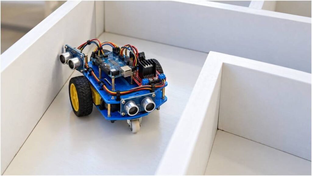
An obstacle-avoiding robot might stop when an object comes within 8 inches. A gripper may reduce motor power when force reaches a safe limit. A drone may change motor speeds repeatedly to correct its angle.
This feedback loop explains how robot sensors work during movement. The robot acts, measures again, and checks whether the action produced the expected result.
To understand where sensing fits within the complete machine, review the main components of a robot, including its controller, actuators, power system, frame, and communication hardware.
How Robot Sensors Work With Distance, Vision, and Touch
Different sensors answer different questions. When I choose one, I begin with the decision the robot must make rather than selecting the most advanced hardware.
Proximity and Distance Sensors
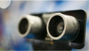
Ultrasonic sensors transmit a high-frequency sound pulse and measure its round-trip travel time. Texas Instruments describes this method as time-of-flight sensing. The calculation divides the measured journey by two because the sound travels to the object and returns.
Infrared sensors usually emit light and measure how much returns. They work well in short-range obstacle detection and line-following projects. However, surface color, angle, sunlight, and reflective materials can affect the reading.
LiDAR uses pulsed laser light to measure range. A scanning unit collects many distance points, allowing software to map walls, furniture, people, and other obstacles. NOAA confirms that LiDAR calculates distance by measuring how long a laser pulse takes to reach an object and return.
Vision Sensors and Computer Vision
A camera converts incoming light into pixel data. Computer vision software then searches those pixels for edges, motion, labels, barcodes, faces, or trained object classes.
Vision provides more context than a single distance sensor, but it needs greater processing power. Glare, shadows, motion blur, and blocked lenses can reduce accuracy. OpenCV documentation shows how image features and trained classifiers can detect objects within video frames.
I avoid using a camera when a simpler sensor can answer the same question faster and with less processing.
Force, Touch, and Tactile Sensors
Touch switches confirm physical contact. Force sensors measure how firmly a robot presses, pulls, lifts, or grips.
A strain-gauge load cell provides precise force feedback. Mechanical deformation changes resistance. A bridge circuit and amplifier turn that change into a measurable voltage. These sensors help robotic grippers handle fragile items and detect collisions.
Encoders, Accelerometers, and Gyroscopes
Encoders measure motor or joint movement. A robot arm compares the commanded position with encoder feedback and corrects any difference.
Accelerometers measure linear acceleration, including gravity’s effect. Gyroscopes measure angular rate. Manufacturers often combine both inside an inertial measurement unit, or IMU. Bosch describes its BMI323 as an IMU that combines acceleration and angular-rate measurements.
These internal devices demonstrate how robot sensors work without detecting an outside object. They help the machine estimate its own tilt, movement, direction, and joint position.
A Worked Example: Turning an Echo Into Distance
Suppose an ultrasonic sensor receives its echo after 5.8 milliseconds. Using an approximate sound speed of 343 meters per second, the controller calculates:
Distance = 343 × 0.0058 ÷ 2
Distance = 0.995 meters
The obstacle is about one meter away. The controller may require three similar readings before slowing the motors. That rule prevents one weak or distorted echo from triggering a sudden turn.
This calculation adds an important detail to how robot sensors work. Sensors often return time, voltage, counts, resistance, or pixels rather than a finished answer. Software converts the raw measurement into useful meaning.
Why Robot Sensor Readings Go Wrong
Sensors operate in imperfect environments. Dust can cover optical lenses. Soft fabric can weaken an ultrasonic echo. Shiny surfaces can redirect light. Motor vibration can distort IMU measurements.
Electrical problems also matter. A noisy power rail, weak ground connection, long wire, or incorrect reference voltage can make stable conditions appear unstable.
Calibration corrects repeatable error. Filtering reduces random noise. Neither can rescue a sensor that does not suit the environment.
Before writing control logic, I check the sensor’s range, field of view, response time, resolution, mounting position, and operating limits.
How Robot Sensors Work More Reliably With Sensor Fusion
Sensor fusion combines evidence from several sources. A mobile robot might use wheel encoders for movement, an IMU for rotation, LiDAR for surrounding geometry, and a camera for object recognition.
Each device covers another device’s weakness. Wheel slip can mislead encoders. Gyroscopes can drift. Cameras struggle in poor light. A narrow distance sensor may miss objects outside its beam.
Fusion does not mean averaging unrelated numbers. Software must align timestamps, coordinate systems, and measurement uncertainty. NIST emphasizes robotics measurement science and performance evaluation because safe autonomy depends on understanding how accurately a system senses and acts.
This layered method explains how robot sensors work in advanced machines. The controller updates its estimate whenever new evidence arrives.
Testing How Robot Sensors Work in Real Conditions
I test one sensor before connecting it to movement. First, I print its raw readings while the robot remains still. I then change one condition, such as distance, angle, lighting, or applied force.
Next, I test the limits. I check the nearest useful reading, the farthest stable range, and likely failure cases. Bright sunlight, dark surfaces, vibration, and uneven floors often reveal problems that a desk test misses.
Only after the readings remain stable do I connect motor commands. I begin at low speed and use conservative thresholds. This approach isolates faults and prevents noisy data from creating unsafe movement.
Your Robot Is Only as Smart as Its Senses
Once I understood how robot sensors work, robot behavior stopped looking mysterious. Every action begins with a physical event, an electrical signal, a digital value, and a software decision.
Start with one sensor and inspect its raw output. Calibrate it where the robot will operate. Add feedback, test failure cases, and increase speed slowly.
Reliable robot behavior comes from trustworthy measurements, not from installing the longest possible sensor list.
Frequently Asked Questions
1. How do robot sensors communicate with a controller?
They send analog voltages or digital data through connections such as I2C, SPI, UART, or direct input pins.
2. How do robot sensors detect obstacles?
Ultrasonic, infrared, LiDAR, radar, and camera systems measure reflected energy to estimate an object’s location.
3. Why do robots use multiple sensors?
Multiple sensors reduce blind spots and provide backup evidence when one measurement becomes unreliable.
4. How robot sensors work without artificial intelligence?
Basic robots use thresholds, programmed rules, and feedback loops; artificial intelligence is optional for complex recognition tasks.