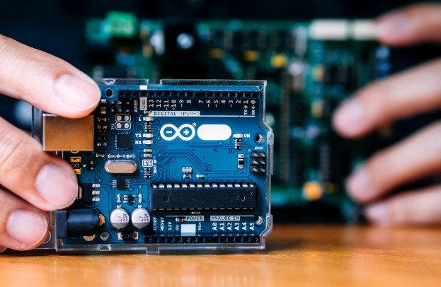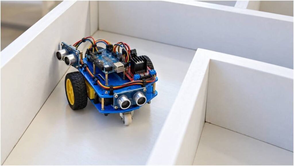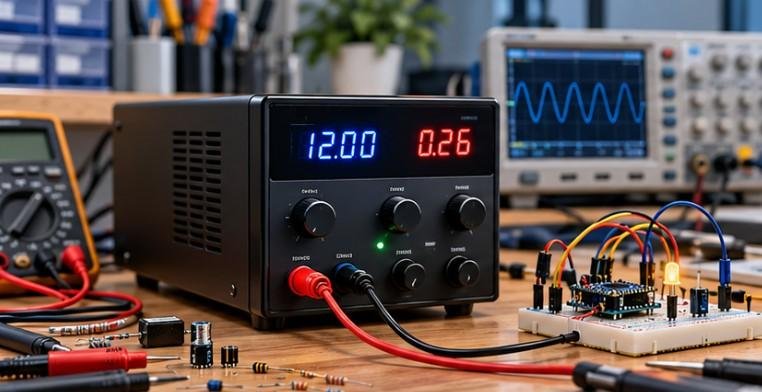
A relay module can look deceptively simple: a few input pins on one side, screw terminals on the other, and a small mechanical relay in the middle. The real challenge is making sure the control voltage, trigger logic, coil supply, and switched load all work together correctly.
When I explain how to use a relay module with low-voltage control, I focus first on separating the control circuit from the load circuit. A 3.3V or 5V GPIO signal does not usually power the device you are switching. Instead, it tells the relay module when to connect or disconnect a separate circuit. That distinction is what makes relay modules practical for Arduino, ESP32, Raspberry Pi, sensors, fans, pumps, lights, and other low-voltage automation projects.
How Does a Low-Voltage Relay Module Work?
A relay module has two main sides.
The first is the control side, where the microcontroller connects. This side typically uses low-voltage power and a GPIO signal.
The second is the load side, where the relay contacts switch the device you want to control.
The microcontroller does not normally power the load itself. Instead, it sends a trigger signal to the relay module. The relay then moves an internal contact between different terminals.
This separation lets a small control signal operate a circuit that may require more current or a different voltage.
Step 1: How Do I Wire the Low-Voltage Control Side?
Most single-channel relay modules use three basic input pins labeled VCC, GND, and IN or SIG.
VCC
VCC supplies power to the relay module. Many common modules use 5V, although some are designed for 3.3V operation.
I always check the module specification before connecting power because the relay coil supply and logic trigger voltage are not always the same.
GND
GND connects to the ground of the controller or power supply when the module design requires a shared ground.
For a typical Arduino relay module, Arduino GND connects to relay GND.
IN or SIG
The IN or SIG pin receives the control signal.
This normally connects to a GPIO pin on an Arduino, ESP32, Raspberry Pi, or another low-voltage controller.
The microcontroller uses this pin to tell the relay when to energize.
What Is the JD-VCC Jumper on a Relay Module?
Some relay modules include both VCC and JD-VCC.
VCC generally supplies the control or input circuitry, while JD-VCC powers the relay coil section.
A small jumper may connect the two together.
When the jumper remains installed, both sections can use the same supply rail. Removing it on a module designed for separate power allows you to supply the relay coil from a different power source.
This can help reduce voltage drops and electrical noise, especially when multiple relay coils energize at the same time.
However, removing the jumper does not automatically guarantee complete electrical isolation. The actual result depends on the board design, optocoupler arrangement, and whether the controller and relay power sections still share a ground.
Step 2: How Do I Connect COM, NO, and NC?
The load side usually has three screw terminals labeled COM, NO, and NC.
COM means common. This is the moving contact inside the relay.
NO means normally open. COM and NO are disconnected while the relay is inactive. When the relay activates, they connect.
NC means normally closed. COM and NC remain connected while the relay is inactive. When the relay activates, that connection opens.
If I want a fan, pump, or lamp to remain off by default, I normally use COM and NO.
For a simple 12V load, the positive wire from the power supply can connect to COM. NO can connect to the positive side of the device. The negative side of the device then returns to the negative terminal of the 12V power supply.
When the relay activates, COM connects to NO and completes the circuit.
This is one of the safest ways to practice how to use a relay module with low voltage control before dealing with more complex loads.
Relay modules are also useful for practical home automation, allowing microcontrollers to control compatible low-voltage devices such as fans, lights, and other small appliances.
Understanding relay wiring, load ratings, and control signals can help you build more useful automation projects while keeping electrical safety a priority.
Step 3: Is My Relay Active-Low or Active-High?
Relay modules generally use either active-low or active-high control logic.
An active-low module turns on when the input signal goes LOW, usually near 0V. It turns off when the input goes HIGH.
An active-high module does the opposite. A HIGH input activates the relay, while LOW releases it.
Many inexpensive Arduino relay modules use active-low logic.
For example, an active-low Arduino relay may work like this:
const int relayPin = 7;
void setup() {
pinMode(relayPin, OUTPUT);
digitalWrite(relayPin, HIGH);
}
void loop() {
digitalWrite(relayPin, LOW);
delay(2000);
digitalWrite(relayPin, HIGH);
delay(2000);
}
In this example, LOW turns the relay on and HIGH turns it off.
I always verify the manufacturer’s documentation instead of assuming every board follows the same logic.
When writing and debugging relay-control code, AI-assisted coding tools can help explain GPIO logic, identify programming errors, and refine microcontroller routines. However, developers should take precautions when using these tools, particularly when sharing project files or troubleshooting sensitive configurations.
This resource about using AI coding tools without exposing private data explains how to protect credentials, API keys, and confidential code while benefiting from AI-assisted development.
Can a 3.3V GPIO Control a 5V Relay Module?
Sometimes yes, but not always.
This is especially important for ESP32, ESP8266, and Raspberry Pi projects because these controllers use 3.3V GPIO logic.
A relay marked 5V usually refers to the relay coil or module supply. It does not automatically mean the signal input requires 5V.
Some 5V relay modules recognize 3.3V as a valid trigger. Others may behave unpredictably or fail to activate.
Before connecting a 3.3V controller, I check the input trigger specification.
If the module does not support 3.3V logic, I use a transistor interface, logic-level driver, or a relay board specifically designed for 3.3V control.
Reliable relay control depends on more than selecting the correct trigger voltage; it also requires understanding how a microcontroller reads and processes electrical signals.
This guide to reading a potentiometer with a microcontroller explains how analog input voltages become digital readings and why signal levels matter in embedded projects.
Understanding these input characteristics can help you troubleshoot control issues and design more dependable interfaces between sensors, microcontrollers, and relay modules.
Why Shouldn’t I Connect a Bare Relay Directly to GPIO?
A bare relay coil may require considerably more current than a microcontroller GPIO pin can safely supply.
That is why a relay module usually includes additional circuitry such as a transistor driver, resistors, a flyback diode, indicator LEDs, and sometimes an optocoupler.
The GPIO only sends the control signal. The transistor handles the relay coil current.
If I use a bare relay, I normally add a transistor or MOSFET driver and a flyback diode.
The flyback diode helps suppress the voltage spike created when the relay coil switches off.
Does an Optocoupler Completely Isolate the Relay?
Not necessarily.
An optocoupler can separate the control signal electrically from another part of the relay circuit, but true galvanic isolation depends on how the board is wired.
If both sections still share the same power supply ground, full isolation may not exist.
That is why I check the relay module schematic before assuming an optocoupler makes the controller completely isolated from the coil section.
Why Does the Relay Click but the Load Stay Off?
If the relay clicks, the input side is probably working.
The problem may be on the output side.
I first check whether the load is connected to COM and NO rather than the wrong terminal. Then I verify the external power supply, screw connections, device polarity, and relay contact rating.
A relay can click normally even when the switched circuit is incomplete.
Why Does My Arduino or ESP32 Reset When the Relay Switches?
A reset usually points to a power or electrical-noise problem.
Relay coils can create a brief voltage drop when they energize. If the controller and relay share an undersized power supply, the controller voltage may dip enough to cause a reset.
I also check for poor grounding, missing decoupling, insufficient supply current, and improper flyback protection in custom relay circuits.
Using a separate relay coil supply can sometimes improve stability.
Relay switching can also introduce electrical disturbances that affect nearby sensors and microcontrollers, particularly when power supplies and grounding are not properly managed.
This is closely related to the issues discussed in why a DC motor causes electrical noise, including voltage fluctuations, electromagnetic interference, and the importance of appropriate suppression techniques. Understanding these effects can help you troubleshoot unexpected resets and build more reliable low-voltage control circuits.
How Do I Choose the Right Relay Module?
I check more than the voltage printed on the relay casing.
The important specifications include the coil voltage, input trigger voltage, contact voltage rating, contact current rating, and the type of load being switched.
Motors and pumps can draw significantly more current during startup than during normal operation, so the relay contacts need enough margin.
For modern electronics projects, I prefer a module with clearly documented 3.3V or 5V input compatibility.
Is It Safe to Use a Relay Module With Household AC?

Relay contacts may be rated for household AC, but working with mains electricity introduces serious shock and fire hazards.
For beginners, I strongly recommend practicing with low-voltage DC loads such as 12V lamps, fans, pumps, or LED strips.
If mains wiring is necessary, power should be completely disconnected before work begins, and the relay, wiring, terminals, and enclosure must all be appropriately rated and insulated.
In the United States, that may involve 120V AC household circuits, so proper electrical safety practices matter.
Frequently Asked Questions
1. Can a 5V relay module switch a 12V device?
Yes. The relay coil voltage and switched load voltage are separate. A 5V relay module can often switch a 12V load as long as the relay contacts are rated for the voltage and current.
2. Can an ESP32 control a 5V relay?
It can if the relay module accepts a 3.3V trigger signal. If it does not, use a suitable transistor or logic-level interface.
3. Why is my relay always on?
The module may use active-low logic, the GPIO input may be floating, or the controller may briefly enter an unexpected state during startup.
4. Do relay modules need flyback diodes?
Most commercial relay modules already include coil suppression. Bare relay coils usually need a flyback diode or another suitable suppression method when used with DC.
5. What is the easiest way to learn how to use a relay module with low voltage control?
Start with a low-voltage DC load, verify VCC and trigger voltage, identify COM, NO, and NC, and confirm whether the module uses active-low or active-high logic before powering the circuit.
Final Thoughts
Relay modules become much easier to understand once I separate the circuit into three parts: the control signal, the relay coil supply, and the switched load.
Most problems come from mixing up these sections, assuming every 5V relay needs a 5V trigger signal, confusing NO with NC, or expecting a GPIO (A General Purpose Input/output) pin to power a bare relay coil directly.
For a reliable project, I verify the input voltage, check active-low or active-high behavior, confirm the contact ratings, and test the circuit with a safe low-voltage load first.
That approach makes relay wiring easier to troubleshoot and helps protect both the controller and the device being switched.