I find few electronics problems more frustrating than a powered board that refuses to communicate. A sensor stays silent, a display shows nonsense, or a motor controller ignores commands.
This USB logic analyzer review for debugging hardware signals focuses on what matters when choosing a tool: readable captures, dependable decoding, practical sampling limits, and software that helps explain the fault.
What a USB Logic Analyzer Actually Reveals
A USB logic analyzer records digital states across several inputs and displays them against time. Protocol decoders translate those transitions into information such as addresses, bytes, and acknowledgments.
That makes it useful for checking whether a microcontroller transmitted a command, whether a peripheral responded, and whether events happened in the expected order.
However, digital traces cannot fully reveal ringing, overshoot, or slow voltage transitions. An oscilloscope remains necessary when the electrical waveform itself needs investigation.
Which Type Offers the Best Value?
Budget Analyzers for Basic Projects
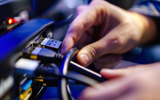
An inexpensive eight-channel analyzer supported by PulseView can be a sensible starting point for slower UART, I²C, and basic GPIO work. Compatibility depends on the actual hardware and software driver.
The compromises often involve probe quality, input protection, thresholds, and acquisition limits. Similar-looking enclosures do not guarantee identical electronics. Check the specific unit’s documentation before connecting it.
DSLogic for More Demanding Captures
The DSLogic range deserves consideration when you need additional channels, onboard capture memory, and more involved triggering.
Models differ significantly. Compare buffer and streaming modes separately, and check the sample rate available with your intended channel count. A family’s highest advertised rate does not describe every capture configuration.
Saleae for Software-Focused Workflows
Saleae belongs on the shortlist when software usability and supported decoding workflows carry substantial weight. Some models also offer analog recording alongside digital capture.
That capability can provide useful context, but its specifications still matter. Limited analog bandwidth does not replace a suitable oscilloscope for investigating fast electrical problems.
Read Sampling Specifications Before Buying
Sample rate describes how frequently the analyzer records an input. It does not equal the maximum signal frequency that the instrument can reliably interpret.
For example, a 24 MS/s acquisition samples approximately every 41.7 nanoseconds. That interval alone cannot guarantee accurate capture of narrow pulses.
For periodic digital signals, four times the signal frequency can serve as an initial sampling guideline. Use more margin when possible, and consider the shortest pulse you need to observe.
Also check input bandwidth, threshold compatibility, and channel restrictions. These details matter more than a large number printed on the enclosure.
Set Up Without Creating Another Fault
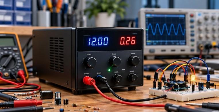
Check the target voltage against the analyzer’s documented operating limits. Adjustable thresholds and maximum safe input voltage describe different things.
Connect the ground lead to the board’s ground reference and keep connections short. Many USB analyzers share ground with the connected computer, so attaching a ground clip to another potential can cause damage.
Power down before attaching probes where practical. Label channels clearly, secure loose hooks, and confirm that connecting the analyzer has not changed circuit behavior through input loading.
Use Protocol Captures to Find Specific Problems
UART: Check Settings Before Blaming Firmware
Capture the transmit line and configure the decoder for the expected baud rate, polarity, parity, and stop bits. Unreadable characters can result from incorrect settings rather than corrupted transmission.
Compare the decoded bytes with the message your firmware intended to send. If you need to inspect or rework connections, choosing the best mini bench vise for circuit board repairs can help keep the board steady.
I²C: Follow the Address and Response
Capture both clock and data. Look for a start condition, the expected address, and acknowledgment behavior.
A missing acknowledgment narrows the investigation toward addressing, wiring, power, or peripheral readiness. It does not identify the cause by itself. Check whether your software displays seven-bit addresses or address bytes.
SPI: Match the Decoder to the Peripheral
Record clock, chip select, and the required data lines. Set clock polarity, clock phase, bit order, and word length from the peripheral documentation.
A plausible decoded value can still be wrong when those settings are mismatched. Compare transactions with the expected register command and response.
Judge Software and Capture Depth Together
A useful interface should make channel naming, zooming, measurements, decoding, searching, and exporting straightforward. Saving configuration alongside captures helps reproduce an intermittent issue later.
Streaming can support longer recordings, but performance depends on USB throughput and the computer. Buffered acquisition provides local storage with finite capacity.
Evaluate both against your actual task: a brief startup sequence and an occasional fault require different recording strategies.
Frequently Asked Questions
1. What matters most in a USB logic analyzer review for debugging hardware signals?
Look for documented input limits, sample rates at the required channel count, useful triggers, software compatibility, and evidence showing how captures help diagnose faults.
2. Can an analyzer measure PWM?
Yes. Suitable software can measure pulse width, period, and duty cycle. Accuracy depends on sampling resolution and capture quality.
3. Does USB connectivity mean it analyzes USB traffic?
No. USB may simply connect the instrument to the computer. Capturing USB traffic requires appropriate electrical capability and decoding support.
My Final Take
My takeaway from this USB logic analyzer review for debugging hardware signals is to buy for the faults you need to investigate. I would start with voltage compatibility, required channels, and software support, then compare capture limits. A useful analyzer turns confusing transitions into evidence you can act on.