A circuit that looks perfectly wired can still sit there doing absolutely nothing. I have seen this happen because of something as small as a loose jumper, a weak battery, a reversed LED, or one connection sitting in the wrong breadboard row. The frustrating part is that several different faults can produce the same symptom, which is why random part swapping usually wastes more time than it saves.
When I need to figure out how to troubleshoot a circuit that does not work, I follow a fixed sequence instead of guessing. I verify the power source, check for open and short circuits, inspect component orientation, confirm ground connections, and then use a multimeter to trace where the expected voltage or signal disappears. That method makes even a confusing circuit much easier to diagnose.
What Should I Check First When a Circuit Stops Working?
I start with safety and power.
Before touching wiring or performing resistance or continuity measurements, I disconnect the power source. On mains-voltage, breaker-panel, or industrial equipment, troubleshooting involves much greater risk and may require qualified electrical personnel and Lockout/Tagout procedures.
For low-voltage electronics, I still verify that the circuit is de-energized before touching exposed conductors or changing components.
Once it is safe, I perform a visual inspection. I look for loose wires, damaged jumper leads, corrosion, cracked solder joints, blown fuses, burned components, melted insulation, or obvious wiring mistakes.
If a component is discolored or unusually hot, that often points toward excessive current or a short circuit.
Is the Problem an Open Circuit or a Short Circuit?
Most circuit faults can be broadly divided into open circuits and short circuits.
An open circuit occurs when the intended electrical path is broken. A disconnected wire, failed switch, cracked solder joint, blown fuse, or damaged breadboard connection can stop current completely.
A short circuit creates an unintended low-resistance path. Current may bypass the load, causing excessive current draw, overheating, blown fuses, or power supplies entering protection mode.
Understanding this difference helps me decide which test to perform next.
How Do I Check the Power Supply Properly?

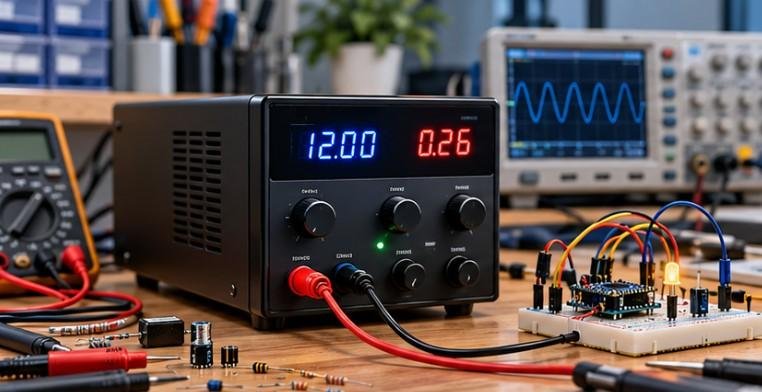
I measure the supply voltage before investigating individual components.
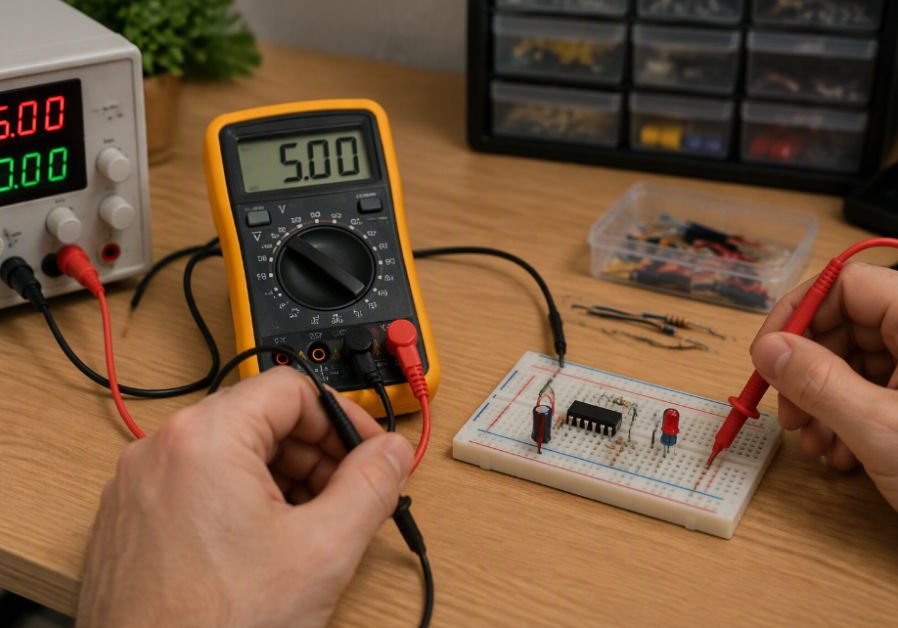
Using DC voltage mode on my multimeter, I place the black probe on circuit ground and the red probe on the positive supply. The measured voltage should match the circuit’s requirements.
I also measure voltage at the breadboard power rails or PCB supply pins rather than assuming voltage reaches them.
Power supply problems are especially important to identify in Raspberry Pi projects that collect data from sensors or monitor electricity usage. An unstable supply or incorrect wiring can lead to unreliable readings and unexpected system behavior.
If you want to see how these principles apply to a practical monitoring application, explore these Raspberry Pi projects for home energy monitoring, which demonstrate how embedded systems can help track household energy consumption.
Why Should I Test the Power Supply Under Load?
A battery or power adapter can appear healthy with nothing connected but fail when the circuit begins drawing current.
For that reason, I measure the voltage again while the circuit is operating. If a 5-volt supply measures correctly without a load but drops significantly when switched on, the supply may be weak, undersized, or damaged.
This test is especially useful with batteries, USB power sources, and inexpensive bench supplies.
How Do I Find Wiring Mistakes in a Breadboard Circuit?
Breadboard wiring errors are extremely common.
I compare the physical circuit against the schematic one connection at a time. Being one breadboard row off can leave a component electrically disconnected even though everything looks correct.
I also check whether the power rails are split in the middle. Many breadboards do not connect the entire positive or negative rail continuously.
LEDs, diodes, electrolytic capacitors, transistors, and integrated circuits also require careful orientation. I verify polarity and pinouts instead of assuming similar-looking components use the same arrangement.
How Can I Find an Open Circuit With a Multimeter?
For continuity testing, I turn the power off.
I place the multimeter in continuity mode and test suspicious wires, switches, PCB traces, solder joints, and jumper connections.
If the meter indicates continuity, the path is electrically connected. If it does not, I investigate that section for a broken wire or poor connection.
Voltage testing can also locate an open circuit while the circuit is safely energized.
What Is the Half-Split Troubleshooting Method?
The half-split method can locate a fault faster than checking every point individually.
I first identify the beginning and end of the electrical path, then measure approximately halfway through it.
If the expected voltage is present at the midpoint, the fault is probably farther downstream. If the voltage is missing, the fault is likely between the source and that midpoint.
I then divide the faulty section again and repeat the process.
This method is especially effective when troubleshooting larger circuits because each measurement eliminates a significant portion of the possible fault locations.
How Do I Find a Short Circuit?

I disconnect power before using resistance or continuity mode.
Then I measure resistance between suspicious points, such as the positive supply and ground.
Very low resistance where it should not exist can indicate a short circuit. I inspect for touching leads, solder bridges, damaged insulation, incorrect breadboard placement, or failed components.
If the circuit contains parallel branches, I can disconnect individual branches one at a time. When the unusually low resistance disappears, I have narrowed the short to that section.
How Do I Troubleshoot Grounding Problems?
Poor grounding can create confusing symptoms.
A circuit may work intermittently, produce incorrect sensor readings, reset a microcontroller, or behave unpredictably when different sections do not share the same ground reference.
When grounding problems affect sensor measurements, it is also important to understand how analog signals become digital readings. Incorrect voltage levels, electrical noise, and unstable reference voltages can all affect the values a microcontroller receives.
This article on how to convert sensor voltage into digital values explains ADC conversion, signal conditioning, reference voltage, and filtering techniques that can help you diagnose unreliable sensor readings.
I make sure the power supply, microcontroller, sensors, drivers, and external modules share the appropriate common ground unless the design specifically requires electrical isolation.
Can Floating Inputs Make a Circuit Behave Randomly?
Yes. Floating inputs are especially important in microcontroller and digital logic circuits.
An input pin that is not connected to a defined voltage can pick up electrical noise and randomly switch between logical states.
I prevent this by using pull-up or pull-down resistors when required. Many microcontrollers also include internal pull-up resistors that can be enabled through software.
If a circuit works sometimes but fails unpredictably, floating inputs are worth checking.
How Do I Separate a Hardware Problem From a Software Problem?
For Arduino, Raspberry Pi Pico, ESP32, and other programmable boards, I simplify the project.
I first confirm that the board has stable power and that the correct pins are connected. Then I test individual hardware components with a simple program.
If an LED, relay, sensor, or motor driver works with basic test code but fails in the complete project, the problem may be in the software rather than the wiring.
I also verify pin assignments, input and output modes, communication settings, and shared ground connections.
When troubleshooting a microcontroller project, it is useful to test output devices separately from the main program.
A relay module, for example, lets a low-voltage control signal switch a compatible external load, but incorrect wiring, incompatible logic levels, or insufficient coil power can prevent it from working properly.
This on how to use a relay module with low-voltage control explains the wiring and safety considerations to check when diagnosing relay-based circuits.
How Should I Test a Suspected Component?

Before replacing a component, I try to confirm that it has actually failed.
I can measure resistor values, test LEDs and diodes using diode mode, check switches with continuity mode, and test jumper wires from end to end.
For more complicated components, I sometimes remove them from the circuit and test them independently.
When replacing a failed component, I use a replacement with the correct voltage, current, power, and other relevant ratings.
Frequently Asked Questions
1. What is the fastest way to find a fault in an electronic circuit?
Start with the power supply, inspect the wiring, verify ground connections, and then trace voltage from the source toward the output. The point where the expected voltage or signal disappears usually identifies the faulty section.
2. Why does my circuit have voltage but still not work?
A voltage reading does not guarantee that the circuit can deliver enough current. You may have an open connection, weak power supply, incorrect ground, reversed component, wrong resistor value, or damaged part.
3. How do I know if my breadboard is causing the problem?
Check continuity between holes that should be connected and verify whether the power rails are split. Worn breadboard contacts can also create intermittent connections.
4. Should the circuit be powered during multimeter testing?
Voltage measurements require power when it is safe to energize the circuit. Resistance and continuity measurements should normally be performed with the power disconnected.
5. What is the best way to learn how to troubleshoot a circuit that does not work?
Use the same sequence every time: inspect the circuit, verify power, check ground, confirm component orientation, test continuity, trace voltage, and isolate the faulty section.
Final Thoughts
Whenever I troubleshoot electronics, I try to prove where the problem is rather than guess what might be wrong. That mindset saves time, protects components, and makes complicated circuits much easier to understand.
The most effective approach is to begin with power and safety, decide whether I am dealing with an open or short circuit, and then use a multimeter to narrow the problem section by section.
Once I know how to troubleshoot a circuit that does not work, even a confusing breadboard or microcontroller project becomes much more manageable. A systematic process turns troubleshooting from trial and error into a repeatable skill.