A robot can pass its first bench test and still fail when a loose cable catches a wheel. I approach how to organize wiring inside a robot as part of the mechanical design because cable placement affects movement, troubleshooting, and repairs.
A reliable layout gives every wire a protected route while keeping connectors accessible. Whether you are building a classroom rover or a competition machine, the following process helps turn tangled wiring into a system you can inspect and maintain.
Plan the Electronics Layout First
Disconnect the battery before rearranging wiring. Position the controller, motor drivers, power distribution hardware, and battery before measuring cable routes. Keep the power switch accessible and leave room to remove components without dismantling the chassis.
Draw a simple connection diagram showing each device and its destination. Record controller ports, connector types, and supply voltages. A basic sketch helps reveal missing connections and prevents wiring from becoming an afterthought.
Create a Practical Routing Example
On a two-wheel rover, place the motor driver near the drive motors and the controller where sensor connections remain accessible. Route battery wiring through a protected chassis corridor. Give front-mounted sensors a separate, clearly identifiable branch.
Keep cables clear of cooling openings, mounting screws, and battery removal paths.
Choose Suitable Cable Management Supplies
Small cable ties work well for fixed bundles. Reusable hook-and-loop straps suit sections that need frequent changes. Clips, cable mounts, and printed brackets provide attachment points where the chassis offers little support.
Spiral wrap or braided sleeving can protect cable groups, while rubber grommets protect insulation where wires pass through panels. Choose sleeves that preserve access to branch connections.
Use secure mechanical mounting for critical supports where practical. Adhesive mounts require clean surfaces, and their suitability depends on temperature, vibration, and the mounting material.
Route Cables Away From Damage
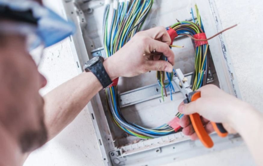
Follow stationary chassis members and protected interior edges. Avoid exposed gears, belts, chains, wheel hubs, hot components, and sharp metal.
Cable routing also depends on the robot’s structural design, since chassis stiffness and controlled flexibility influence how wires move during operation.
Where possible, give sensitive signal cables a different route from high-current motor wiring. Follow controller and sensor documentation for shielding, grounding, and communication-cable requirements rather than assuming every circuit needs the same treatment.
Bundle cables by destination or subsystem. A removable arm should have an identifiable harness instead of wires scattered through unrelated bundles.
Set Cable Length and Strain Relief
Measure routes with components installed. Cables need enough length for connection, servicing, and intended movement without leaving loose coils near mechanisms.
A useful rule when learning how to organize wiring inside a robot is to support the cable before its connector. The mounting point should absorb ordinary pulling forces instead of transferring them to a board socket or solder joint.
Leave a gentle bend between the support and connector. Tighten ties enough to hold fixed wiring without crushing insulation. Trim tie ends flush and avoid attaching cables so frequently that repairs become difficult.
Handle Moving Parts Separately
An arm, lift, or gripper needs a controlled cable loop that accommodates its entire travel. Secure the harness appropriately on the stationary and moving sections, keeping the bending region clear of pinch points.
Planning cable routes around robotic arms and other articulated mechanisms requires an understanding of how each joint moves and how that movement affects the wiring harness. The number and arrangement of a mechanism’s axes determine its available movements, influencing cable flexibility, routing paths, and potential pinch points.
Understanding robot axes versus degrees of freedom can help you anticipate joint movement, organise cables around articulation points, and reduce the risk of twisting or mechanical interference.
Cable routing around moving mechanisms also requires careful consideration of the space a robot occupies during operation. As an arm, lift, or mobile platform turns, its components may approach surrounding structures or extend beyond their stationary footprint, creating potential clearance and interference issues.
Understanding how to calculate a robot’s turning radius helps you assess manoeuvring space and plan cable paths that remain clear of obstacles throughout the robot’s intended movements.
Use cable intended for repeated flexing where movement is frequent. Follow its specified bend radius; a protective sleeve cannot make unsuitable wire resistant to fatigue.
Check Both Movement Limits
With power isolated and the mechanism safely supported, check cable behavior throughout its permitted movement where manual movement is appropriate. Do not force mechanisms that resist back-driving.
Watch for tension, rubbing, twisting, and loops entering gears. Continuous rotation requires a suitable electrical transfer arrangement or a defined rotation limit; extra slack alone cannot prevent eventual twisting.
Label Connections and Preserve Access
Label both ends of each cable with its function and port. Names such as “left motor” or “front sensor” help connect the physical wiring to your program.
Clear wiring labels also support reliable robot control by helping you trace connections between sensors, controllers, and actuators during troubleshooting. When diagnosing unexpected movement or inconsistent responses, it is important to determine whether the issue originates in the wiring, the control logic, or the feedback system.
Understanding the key differences between open-loop and closed-loop robotics can help you identify how feedback influences system behaviour and make electrical inspections and control-system debugging more systematic.
Use consistent color conventions, but verify polarity and pinouts instead of trusting color alone. Photograph the finished layout and update your diagram after changes.
Keep connectors accessible and retain appropriate service slack. Frequently used programming ports may benefit from a secured extension that reduces handling of the original socket.
Inspect Before Powered Testing
Check connector seating, exposed conductors, damaged insulation, and clearance around moving parts. Confirm polarity and use appropriate electrical checks before reconnecting power.
Begin powered testing with the robot supported appropriately and the workspace clear. Observe wiring during controlled movement, then inspect again after operation.
Avoid hiding questionable connections inside sleeves or using cable ties to compensate for damaged connector latches.
Frequently Asked Questions
1. What is the first step in how to organize wiring inside a robot?
Disconnect power, position the electronics, and sketch the connections. Plan routes before cutting or securing cables.
2. Can I bundle every cable together?
Group cables thoughtfully by destination and electrical requirements. Follow device guidance when routing sensitive signals near motor wiring.
3. How much slack should moving cables have?
Allow enough for full permitted travel without connector tension or snagging. The required length depends on the mechanism.
Final Thoughts
I judge wiring by how easily I can inspect a connection, replace a component, and operate every mechanism without pulling a cable. Start with deliberate routes, add protection where needed, and document the finished layout. Those habits make the next repair faster and help keep a small wiring problem from interrupting an otherwise successful build.