A robot chassis can look flawless on a workbench and still drive like a shopping cart with a damaged wheel. Small errors in motor alignment, wheel spacing, weight distribution, and printed-layer orientation can matter more than the Arduino code controlling it.
Learning how to 3d print robotic chassis for arduino projects is therefore less about making a plastic rectangle and more about designing a predictable mechanical platform. A good chassis keeps wheels aligned, protects electronics, leaves room for wiring, and places the battery where its weight improves rather than ruins handling. For most hobby robots, a simple two-wheel differential-drive layout is the best place to begin.
Table of Contents
ToggleWhy Chassis Geometry Matters More Than It Looks
Carnegie Mellon University’s Robotics Institute describes differential drive as a system in which two independently controlled mobile motors provide forward, reverse, and rotational movement. Its researchers also note that caster friction and wheel arrangement can influence turning behavior.
That explains why two Arduino robots running identical code may move differently.
The chassis controls the physical relationship between:
- drive wheels;
- motor shafts;
- caster;
- battery;
- Arduino;
- motor controller;
- sensors.
If the left motor sits even slightly crooked, the robot may continuously drift. If a heavy battery is mounted high above the deck, rapid turns can make the platform unstable.
The goal should be a low, rigid, symmetrical structure rather than simply the smallest possible frame.
Start With the Hardware, Then Draw the CAD Model
Do not design the chassis and hope your components fit afterward. Lay the actual Arduino, motors, battery holder, motor driver, switches, sensors, and caster on paper first. Measure them with digital calipers if available.
A beginner two-wheel robot commonly contains an Arduino Uno or Nano, two geared DC motors, two wheels, one caster, a motor driver, and a battery pack. Give connectors and wires more room than their physical dimensions suggest. A perfectly fitted Arduino is useless if you cannot insert its USB cable.
Build Serviceability Into the Design
Useful CAD features include:
- mounting bosses for circuit boards;
- slotted motor mounts;
- cable-routing holes;
- zip-tie slots;
- recessed nut traps;
- battery straps;
- an accessible power switch;
- removable sensor brackets.
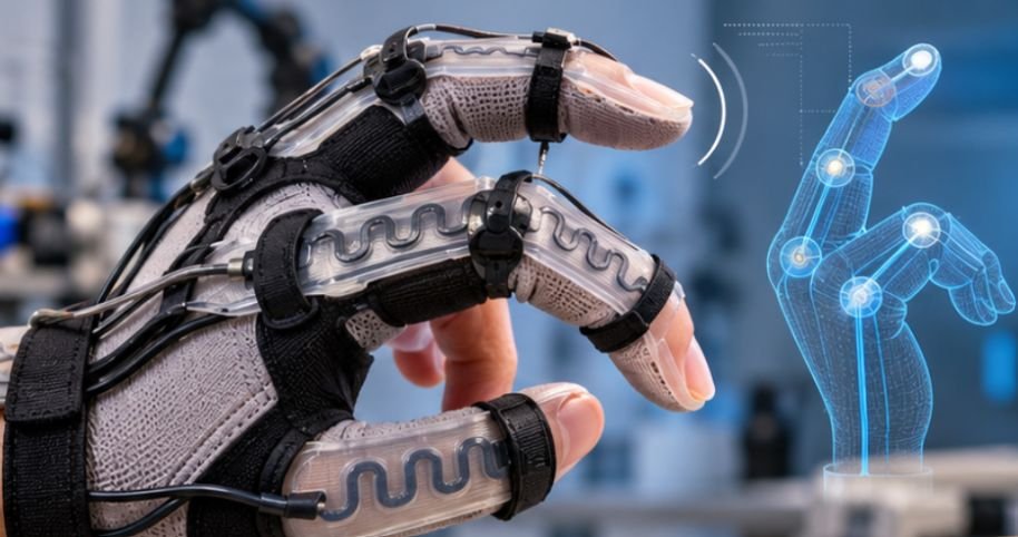
If your Arduino robot needs to detect movement or monitor joint deformation, you can also explore how to 3D print conductive trace sensors for wearable robotics, including flexible sensor designs that integrate sensing capabilities directly into printed components.
For holes that receive machine screws, do not automatically model them at the screw’s exact nominal diameter. FDM printers rarely reproduce tiny holes perfectly, so test-print a small hole gauge before committing to a six-hour chassis.
If you are new to the manufacturing process itself, this explanation of how 3D printing works provides useful background before designing functional mechanical parts.
A Practical Chassis Layout
For a small indoor rover, imagine a rectangular deck about 150–180 mm long and 100–140 mm wide. Those dimensions are only a starting point; the actual motors, wheels, and battery should determine the final footprint. Place the two drive-motor shafts on the same axis.
Position the battery low and reasonably close to that axle. The Arduino and lightweight sensor boards can occupy the remaining deck space. A caster at the opposite end creates the third ground-contact point.
Carnegie Mellon Robotics Academy teaches that the drivetrain includes the chassis, motors, wheels, gears, and transmission components, and that drivetrain selection should depend on terrain, speed, and payload requirements. That is an important design lesson: build around what the robot must do.
PLA or PETG? Choosing the Chassis Material
For most classroom and indoor prototypes, PLA is perfectly reasonable. It prints easily, remains dimensionally stable, and produces stiff mounting structures.
PETG is useful when the robot will encounter warmer environments, repeated impacts, or greater mechanical abuse. It is generally tougher but may require more careful print tuning.
A reasonable starting configuration is:
| Setting | Practical Starting Point | Why |
| Layer height | 0.20 mm | Good balance of detail and speed |
| Perimeters | 3–4 walls | Adds strength around the chassis edges |
| Infill | 20–30% | Usually sufficient for a lightweight rover |
| Top/bottom layers | 4–5 | Strengthens mounting surfaces |
| Supports | Only where needed | Reduces cleanup and dimensional errors |
These are starting points rather than engineering constants. Printer calibration, filament formulation, geometry, nozzle diameter, and load direction all affect the finished part.
NIST research into fused-filament fabrication has found that print conditions including layer height, nozzle temperature, and extrusion behavior can influence geometry and interlayer bonding.
How to 3D Print Robotic Chassis for Arduino Without Weak Motor Mounts
Printing the main deck flat on the build plate is usually the simplest approach. Motor brackets deserve more thought. Thin vertical tabs can fail along layer boundaries, particularly when motors transmit vibration and sudden torque into them.
Add fillets where brackets meet the deck and use triangular gussets around tall mounts. Increasing wall count around structural features is often more useful than filling the entire chassis with extremely dense infill.
NIST describes material extrusion as an additive process that creates structures layer by layer. That layered construction enables complex geometry but also means designers must consider how loads cross deposited layers.
Assemble the Mechanical System Before Wiring It
Install both motors first. Put the chassis on a flat surface and confirm that the wheel axles are parallel. Attach the wheels and caster, then roll the unpowered chassis by hand. It should move smoothly without one wheel visibly fighting the other.
Next install the battery, motor driver, Arduino, and sensors. Keep motor wires away from spinning wheels and leave enough slack for maintenance without creating loose loops that can snag.
For small DC-motor robots, compact drivers such as a TB6612FNG-style board can save space compared with older, bulky driver modules. Larger motors require drivers sized for their actual operating and stall currents.
Run Three Tests Before Adding Autonomous Code
Do not begin with obstacle avoidance or complicated navigation.
1. Straight-Line Test
Command both motors at equal speed and drive several feet across a smooth floor. Consistent drifting often indicates unequal motors, wheel diameter differences, mechanical alignment problems, or unequal motor output.
2. Rotation Test
Command one wheel forward and the other backward. A differential-drive robot should rotate approximately around the midpoint between its drive wheels. Jerking or wandering suggests friction or geometry problems.
3. Flex Test
Hold the assembled chassis and gently twist opposite corners. If the frame visibly flexes, sensor readings and wheel alignment may change while driving. Add ribs or thicker perimeter structures rather than blindly increasing infill everywhere.
Do Not Treat Battery Mounting as an Afterthought
A battery is often the heaviest component on a small Arduino rover, so its position strongly affects the center of gravity.
Mount it low and securely. Lithium-ion or lithium-polymer batteries also require additional care. OSHA warns that lithium-ion cells contain considerable stored energy and can enter thermal runaway following damage, excessive temperatures, short circuits, or improper charging.
Use an appropriate charger, prevent wires from rubbing against moving components, and never design a battery compartment that crushes or punctures the cell.
Common Chassis Mistakes Worth Avoiding
The most frequent failure is designing for appearance instead of access. USB ports, screw heads, motor terminals, batteries, and switches eventually need to be reached.
Another mistake is making every bracket permanent. Modular sensor mounts let you replace an ultrasonic sensor with infrared, line-following, camera, or LiDAR hardware without printing the entire chassis again.
When designing robotic components that must flex repeatedly without cracking, careful material selection and stress management are essential. Learn how to 3D print flexible hinges that bend without breaking to apply these principles to moving joints and other flexible mechanisms in functional printed assemblies.
Finally, do not assume more plastic automatically means more strength. Better geometry—ribs, fillets, gussets, wider mounting surfaces, and sensible print orientation—usually produces a lighter and more useful robot.
Frequently Asked Questions
1. What filament is best for an Arduino robot chassis?
PLA is excellent for most indoor prototypes. PETG is preferable when increased toughness, temperature resistance, or impact resistance matters.
2. How much infill should a robot chassis have?
About 20–30% is a useful starting range. Structural walls, ribs, gussets, and additional perimeters often improve practical strength more efficiently than extremely high infill.
3. Can I mount an Arduino directly onto a printed chassis?
Yes. Use printed standoffs or spacers so solder joints and exposed contacts beneath the board cannot touch conductive objects or become damaged.
4. Does a 3D-printed robot need a caster wheel?
Not always, but a two-wheel differential-drive chassis normally needs a third support point. A caster or ball caster provides that support while allowing the robot to turn.
Build the Chassis as Part of the Robot, Not Around It
The most successful Arduino chassis is rarely the most complicated one. It is the frame that keeps two motors aligned, puts heavy components low, provides predictable traction, and lets you repair the electronics without dismantling everything.
Start with the motors, wheels, battery, and board dimensions. Print a simple version, perform straight-line and rotation tests, then revise the CAD model based on what the physical robot reveals. That iterative approach is the real advantage of how to 3d print robotic chassis for arduino projects: mechanical mistakes can become improved designs instead of permanent hardware.