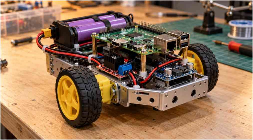
A robot that reboots whenever its wheels start has a power problem before it has a coding problem. My approach to how to power a raspberry pi robot with 18650 batteries starts with two separate branches: regulated power for the Pi and motor power through a suitable driver.
A protected two-cell pack can supply both branches. However, the battery voltage, converter rating, charger, and wiring must work together.
Here’s the design I would choose for a small two-wheel robot, including the connections that often get missed.
Match the Battery Pack to Your Raspberry Pi
A typical 18650 lithium-ion cell has a nominal voltage around 3.6–3.7V and reaches 4.2V when fully charged. Its minimum operating voltage depends on its datasheet.
Two cells in series form a 2S pack: approximately 7.2–7.4V nominal and 8.4V fully charged. Series wiring increases voltage; it does not double amp-hour capacity.
Neither one cell nor a raw 2S pack belongs on the Pi’s 5V input.
The Pi 4 calls for a 5V, 3A supply. Raspberry Pi recommends 5V, 5A for the Pi 5; a 3A supply limits available peripheral power. Check the official Raspberry Pi power requirements before selecting hardware.
For a Pi 5, a converter’s “5A” label alone does not provide USB-C Power Delivery negotiation. Use a power board explicitly supporting your model.
Battery HAT or DIY Power System?
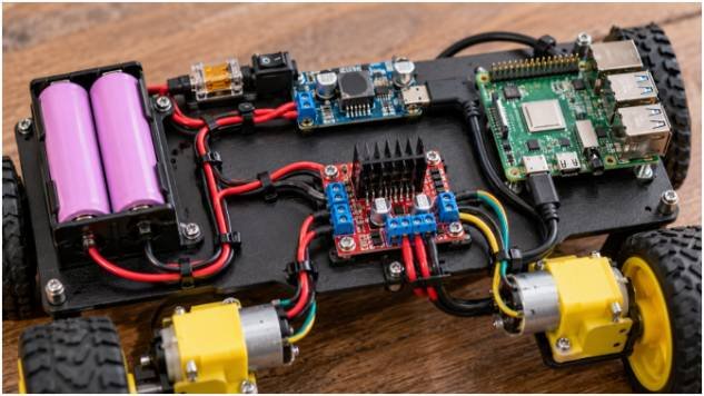
I would choose a battery HAT when compact assembly matters more than custom wiring. Check its continuous output, supported cells, cooling needs, and mounting clearance.
A battery holder on a board does not guarantee charging, balancing, reverse-polarity protection, or uninterrupted operation. Verify each feature separately.
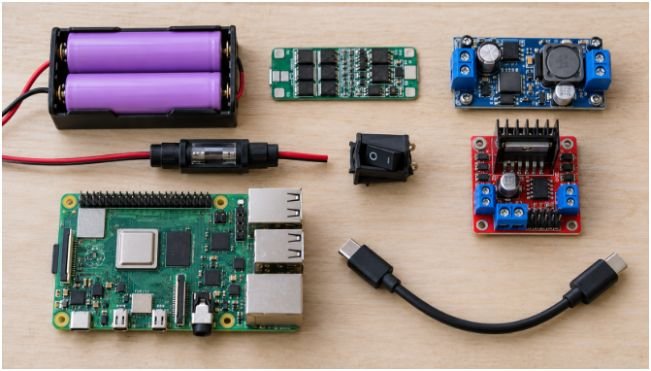
For a robot with demanding motors, a DIY split supply offers more control. The protected pack feeds the motor driver and a dedicated buck converter in parallel.
These branches share a battery, so they are not electrically isolated. Good routing still matters.
The same regulated-power planning helps with a Raspberry Pi home security camera with OpenCV when cameras and processing increase demand.
Choose Your 2S Battery Protection and Buck Converter
My starting point would be a professionally assembled, protected 2S pack with matched cells and a compatible charger.
For a holder-based build, use matching cells with similar age, capacity, charge level, and discharge capability. Avoid damaged wraps and unidentified reclaimed cells.
A suitable 2S battery management system should monitor both cells and provide the required protection. Confirm balancing separately; not every BMS includes it.
A BMS is not a charger. Standard 4.2V-per-cell lithium-ion chemistry requires an appropriate 8.4V CC/CV charging system. Texas Instruments’ two-cell charging documentation illustrates why charging and power-path management require dedicated circuitry.
Choose a synchronous buck converter with documented continuous output at your operating temperature. Verify regulation near the pack’s lowest permitted voltage.
I would not assume a small LM2596 module can continuously power a loaded Pi merely because its listing says “3A.”
Size the pack, protection circuit, switch, and wiring for the Pi load plus motor startup and stall current.
Wire the Battery, Raspberry Pi, and Motor Driver
Connect the Protected Power Rails
Disconnect the battery while assembling. Use the BMS manufacturer’s connection order and terminal diagram; labels vary.
For a conventional 2S protection board, B− connects to the cell stack’s negative end, the midpoint terminal connects between cells, and B+ connects to the positive end. Loads connect to the designated protected output terminals.
Do not return load current directly to B− when the board requires P−. That can bypass protection.
From the protected output, make these connections:
- Protected positive → appropriately rated fuse near the pack → master switch.
- Switch output → buck converter IN+ and motor driver VM.
- Protected negative → ground junction → buck IN− and driver GND.
- Buck OUT+ → Pi power input through a suitable power cable.
- Buck OUT− → Pi power ground.
This assumes a non-isolated buck converter. Keep motor return wiring separate from the Pi’s return until the ground junction.
Set the converter around 5.1V before connecting the Pi, then verify voltage under load. Prefer a purpose-built USB power lead over an improvised chopped cable.
GPIO power through physical pin 2 or 4 and ground pin 6 requires extra care. It bypasses the normal power connector and requires independent protection against wiring errors and backfeeding.
Connect the TB6612FNG Logic and Motors
The following mapping uses BCM GPIO numbers, with physical header positions in parentheses.
Connect Pi 3.3V, physical pin 1, to driver VCC. Connect driver GND to the shared ground.
For the left motor, connect GPIO18 (12) to PWMA, GPIO23 (16) to AIN1, and GPIO24 (18) to AIN2. Connect its leads to AO1 and AO2.
For the right motor, connect GPIO19 (35) to PWMB, GPIO22 (15) to BIN1, and GPIO27 (13) to BIN2. Connect its leads to BO1 and BO2.
Connect GPIO25 (22) to STBY and hold it low until software is ready.
The Pololu TB6612FNG documentation explains its separate logic supply and standby input. Check its current limits against your motors’ stall current.
Raw 8.4V motor power is suitable only when the motors and driver support it.
Adjust the Wiring for an L298N
Use ENA and ENB instead of PWMA and PWMB, removing their enable jumpers for GPIO speed control. Use IN1–IN4 for direction.
The L298 accepts TTL-level inputs but wastes more voltage and power than many modern drivers. Its manufacturer datasheet specifies the relevant thresholds and voltage losses.
Follow your module’s regulator instructions. “Below 12V” alone does not guarantee reliable onboard 5V regulation as a 2S pack discharges. Never parallel its active 5V output with the buck output.
Calculate Runtime Before Buying More Cells
Consider two 3,000mAh, 3.6V cells in series.
Nominal energy equals 7.2V × 3Ah = 21.6Wh.
Assume the Pi averages 6W and its converter operates at 90% efficiency. That branch draws approximately 6.7W from the pack.
If motors and their driver average another 5W, total demand reaches 11.7W.
Estimated runtime equals 21.6Wh ÷ 11.7W, or about 1.85 hours. Reserving 20% for practical losses and shutdown reduces the planning estimate to roughly 1.5 hours.
This is a worked estimate, not a measured result. Terrain, motor load, temperature, and cell condition change runtime.
Similar budgeting applies to battery-backed home automation projects with Raspberry Pi.
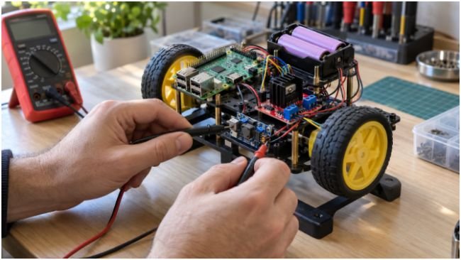
Test for Voltage Drops Before Driving
Start with the wheels raised. Test the Pi alone, then each motor, then both motors starting together.
Check voltage at the Pi, converter temperature, and battery current. Run vcgencmd get_throttled to inspect supported undervoltage and throttling flags.
A correctly polarized 470–1,000µF capacitor near driver VM and GND may help with brief disturbances. Use a suitable voltage rating, such as 16V. It cannot replace adequate battery current or proper motor suppression.
Choose wire size from current, length, and acceptable voltage drop. Thin jumper wires belong on logic connections, not motor supply paths.
Add battery monitoring through an appropriate ADC or monitoring board. Shut down cleanly before protection disconnects the pack.
Give Your Robot Power, Not Drama
I would finish the power system before tuning navigation code. Stable voltage makes every later fault easier to diagnose.
Verify polarity, test simultaneous motor starts, and record actual current. Then run sudo shutdown -h now, wait for shutdown, and disconnect power.
Frequently Asked Questions
1. Can one 18650 battery power a Raspberry Pi robot?
Yes, with a suitable boost supply and protection, provided the cell supports the combined current demand.
2. Can I charge a 2S pack with a TP4056?
No; a standard TP4056 module charges one lithium-ion cell, not a two-cell series pack.
3. Can the robot run while its batteries charge?
Only when the charging system explicitly supports the load through suitable power-path management.
4. Why does my Raspberry Pi restart when motors start?
Battery sag, converter limits, cable losses, or motor interference can pull its supply below a reliable operating level.