A buzzing stepper motor can look busy while going nowhere. I approach how to control a stepper motor with esp32 and a4988 by checking three things first: coil pairs, current limit, and pulse timing.
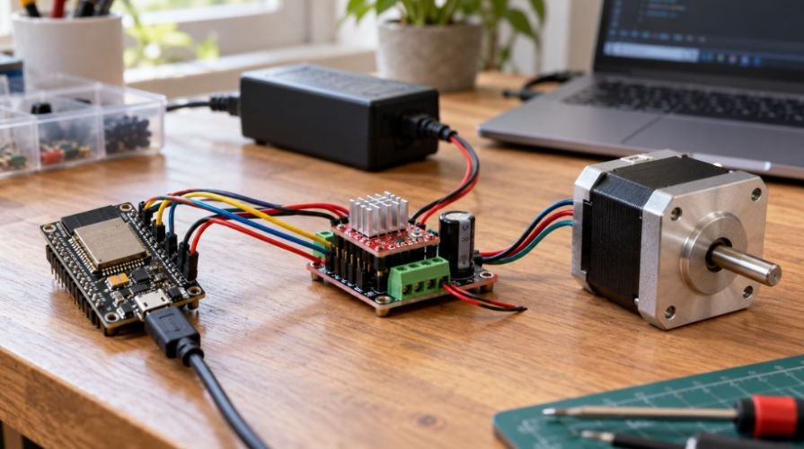
The ESP32 sends STEP and DIR signals. The A4988 switches the motor windings using a separate power supply. That division lets a small controller command a motor without powering it through GPIO pins.
My starting point is deliberately modest: one unloaded revolution forward, then one backward. Prove that behavior before adding mechanisms or wireless controls.
Gather the Parts Before Powering Anything
Use a classic ESP32-WROOM development board, an A4988 carrier, and a four-wire bipolar stepper motor. A 1.8-degree NEMA 17 makes the calculations straightforward. NEMA 17 describes frame size, not current rating.
You also need a regulated 12V DC adapter, a multimeter, suitable wiring, and a 100 µF electrolytic capacitor. For a US workbench, choose an enclosed adapter rated for 120V AC input. Never connect household AC to the driver.
Select the adapter’s current capacity for your operating conditions and driver losses. Add cooling appropriate to your carrier’s documented limits.
The Allegro A4988 datasheet specifies compatible logic levels and control timing. Feed VDD from ESP32 3V3 so both devices share a 3.3V logic reference.
ESP32 A4988 Wiring: Give Every Pin a Job
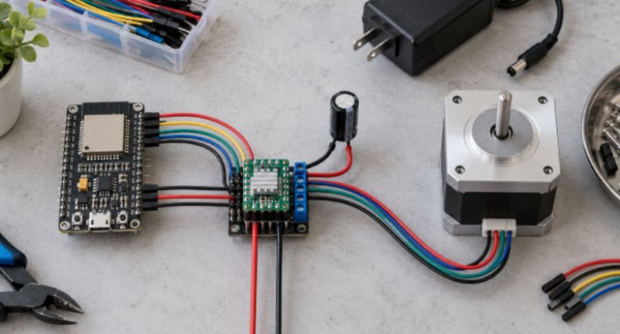
Disconnect USB and motor power before wiring. Use the carrier’s printed pin labels; clone layouts and potentiometer positions vary.
| A4988 connection | Connect to |
| VMOT | External 12V positive |
| Motor GND | External supply negative |
| VDD | ESP32 3V3 |
| Logic GND | ESP32 GND, joined to supply negative |
| STEP | ESP32 GPIO25 |
| DIR | ESP32 GPIO26 |
| RESET and SLEEP | Join together and connect to 3V3 |
| ENABLE | GND for this basic test |
| 1A and 1B | First motor coil |
| 2A and 2B | Second motor coil |
| MS1, MS2, MS3 | GND for full-step operation |
Place the capacitor directly between VMOT and motor GND, with its negative stripe toward GND. A 100 µF, 25V capacitor suits this 12V example. Use an appropriate higher voltage rating if changing supplies.
Keep motor-power leads short. The Pololu carrier guide explains how supply wiring can generate destructive voltage spikes. It recommends at least 47 µF near the board; 100 µF is a practical choice.
I choose GPIO25 and GPIO26 for the classic ESP32 because GPIO12 has a boot-strapping role. Check Espressif’s GPIO documentation before substituting pins. ESP32-C3 and S3 boards require their own pin checks.
Identify the NEMA 17 Coil Pairs
With the motor disconnected, measure resistance between wires. Two wires showing a low, finite resistance belong to one coil. Separate coils should show no continuity.
Connect each identified pair to its own output pair. Do not trust wire colors alone.
Never unplug or reconnect motor wires while powered. Switch off both supplies and allow capacitors to discharge first.
Set the A4988 Current Limit With Vref
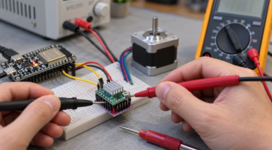
Motor current and supply current are different measurements. Set the winding current limit using the motor specification and your carrier’s sense resistance.
The relationship is:
Vref=8IlimitRsense
Use amps and ohms. Resistor markings R050, R068, R100, and R200 represent 0.050, 0.068, 0.100, and 0.200 ohms. The current-limit equation comes from Allegro’s driver documentation.
Board color does not establish resistance. Pololu lists 0.068-ohm resistors for its carriers manufactured since 2017; older versions used 0.050 ohms.
A Worked Current-Limit Example
Suppose your motor permits 1.0A per phase. I would begin with a target limit of 0.8A, provided the carrier supports that continuously.
For R100:
Vref=80.80.100=0.64V
For R068:
Vref=80.80.0680.44V
An 80% starting point reduces current but does not guarantee safe temperatures. Cooling, airflow, and board construction still matter.
Disconnect the motor with power off. Power the carrier as its documentation requires, then measure between GND and the designated Vref point. Use the potentiometer’s metal top only if your carrier identifies it as Vref.
Adjust gradually with an insulated tool. Avoid shorting adjacent contacts. Power everything off before reconnecting the motor.
Upload the ESP32 Stepper Motor Code
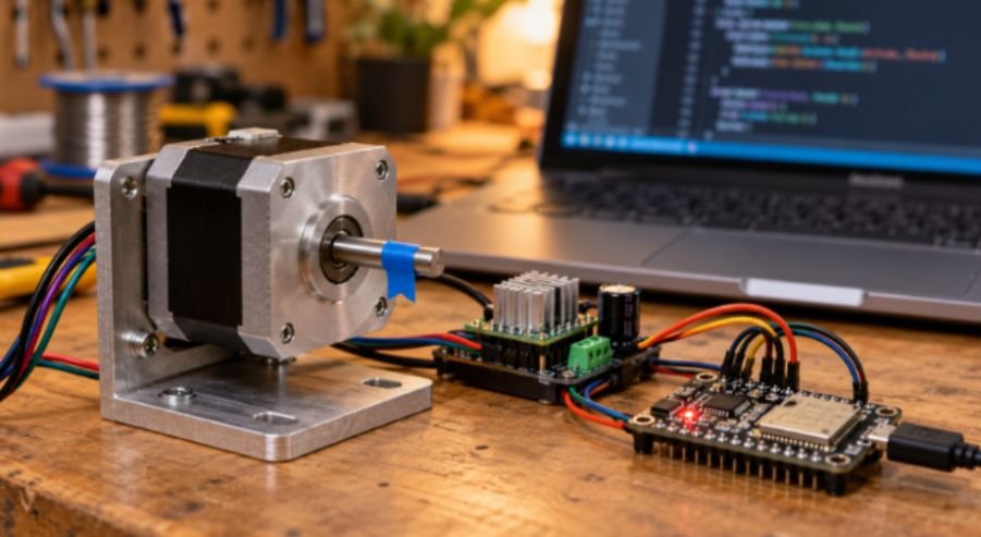
Install Espressif’s ESP32 package in Arduino IDE. Select your actual board and serial port.
This sketch uses built-in Arduino functions without an additional motor library:
constexpr int STEP_PIN = 25;
constexpr int DIR_PIN = 26;
constexpr int STEPS_PER_REV = 200;
constexpr int MICROSTEPS = 1;
constexpr int PULSES_PER_REV =
STEPS_PER_REV * MICROSTEPS;
void moveMotor(bool direction, int pulses) {
digitalWrite(DIR_PIN, direction);
delayMicroseconds(5);
for (int i = 0; i < pulses; ++i) {
digitalWrite(STEP_PIN, HIGH);
delayMicroseconds(1000);
digitalWrite(STEP_PIN, LOW);
delayMicroseconds(1000);
}
}
void setup() {
digitalWrite(STEP_PIN, LOW);
digitalWrite(DIR_PIN, LOW);
pinMode(STEP_PIN, OUTPUT);
pinMode(DIR_PIN, OUTPUT);
delay(10);
}
void loop() {
moveMotor(HIGH, PULSES_PER_REV);
delay(1000);
moveMotor(LOW, PULSES_PER_REV);
delay(1000);
}
Each rising STEP edge advances one selected step increment. The A4988 requires minimum HIGH and LOW widths of 1 microsecond; this sketch uses 1,000 microseconds each.
Mark the shaft and check its travel. A 1.8-degree motor should complete one revolution per move in full-step mode.
This blocking sketch is a commissioning test. Add acceleration and nonblocking motion control before combining demanding movement with Wi-Fi or sensor tasks.
Microstepping and Motor Speed: Do the Math
Read MS1, MS2, and MS3 in that order:
| MS1 | MS2 | MS3 | Mode | Pulses/revolution, 1.8° motor |
| LOW | LOW | LOW | Full | 200 |
| HIGH | LOW | LOW | Half | 400 |
| LOW | HIGH | LOW | Quarter | 800 |
| HIGH | HIGH | LOW | Eighth | 1,600 |
| HIGH | HIGH | HIGH | Sixteenth | 3,200 |
These settings follow the A4988 microstepping truth table. Use 3V3 for HIGH. Change wiring with power off, then update MICROSTEPS to match.
Here is my calculation check: the sketch produces approximately 500 pulses per second, ignoring software overhead.
\[ \text{RPM}=\frac{60\times\text{pulse frequency}} {\text{pulses per revolution}} \]
Full-step operation gives about 150 RPM. Sixteenth-step operation gives about 9.4 RPM at the same pulse frequency.
Matching 150 RPM at sixteenth-step requires 8,000 pulses per second. That is a timing requirement, not proof the motor can achieve it under load.
Microstepping improves command resolution and often smoothness. It does not guarantee proportionally better positioning accuracy or greater torque.
Fix Buzzing, Missed Steps, and Overheating
Buzzing without rotation warrants a coil-pair check first. Then verify common ground, RESET/SLEEP levels, and the current setting.
For missed steps, reduce speed and remove the mechanical load. Add acceleration before increasing current.
For overheating or repeated stopping, check cooling and reduce current. Thermal shutdown is protection, not an operating strategy.
For ESP32 resets, inspect power distribution and grounding. Keep motor-current paths away from the controller’s supply wiring.
Power stability, reliable wiring, and careful troubleshooting are equally important in other microcontroller-based projects involving connected devices and automated monitoring. A Raspberry Pi home security camera with OpenCV demonstrates how a single-board computer can process camera feeds and support intelligent home surveillance. Exploring this project alongside ESP32 motor control can help makers understand the different roles of microcontrollers and single-board computers in practical automation systems.
For incorrect travel, compare the motor’s step angle, MS pin settings, and code multiplier. Pulse counting assumes no steps were lost; absolute positioning requires homing or feedback.
Make It Spin, Then Make It Useful
I would earn one reliable revolution before chasing clever automation. Record the resistor value, Vref, microstep setting, and pulse rate together.
The same power-planning habits help a smart plant watering system using esp32. A bipedal walking robot adds harder demands around coordination, weight, and torque.
Once basic stepper motor control is reliable, the next challenge is applying motor movement to a robot that can operate under real-world conditions.
A solar-powered crawling robot build offers a practical example of combining mechanical movement, motor control, and power management in a mobile robotics project.
Understanding these additional design considerations can help makers progress from testing individual motors to developing autonomous robotic systems.
The ESP32 can also serve as the controller for practical automation projects that combine sensors, actuators, and timed operations.
For example, a DIY smart plant watering system using ESP32 applies the same microcontroller-based approach to monitor plant conditions and automate watering.
Exploring this type of project is a useful next step toward integrating motor control with sensor-driven tasks and real-world automation.
Your next move: verify repeatable unloaded travel, then introduce the real load gradually.
Frequently Asked Questions
1. Can an ESP32 control an A4988 without a level shifter?
Yes, when the A4988 VDD uses 3.3V and both devices share ground.
2. Can I power a NEMA 17 from the ESP32 USB connection?
Use a separate suitable motor supply connected to VMOT, not the ESP32’s USB or 3V3 output.
3. What Vref should I use for a 1.7A NEMA 17?
Calculate it from the chosen current limit and actual sense resistance, respecting the carrier’s thermal capability.
4. Why does my ESP32 stepper lose position?
Excess speed, abrupt starts, insufficient torque, or binding can cause missed steps; add acceleration and homing.