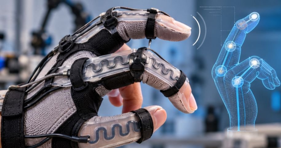
A wearable robot does not always need a bulky encoder or rigid force sensor to understand how a human joint is moving. A thin strip of conductive material printed directly into a flexible polymer can act as both the mechanical structure and the sensor.
That is the attraction behind learning how to 3d print conductive trace sensors for wearable robotics. Using conductive TPU, carbon-filled filament, printable conductive inks, and flexible substrates, makers can create custom strain and pressure sensors that bend with gloves, braces, exoskeleton joints, and soft robotic components.
The difficult part is not simply making plastic conduct electricity. It is making its electrical response predictable after hundreds or thousands of bends.
Why Printed Conductive Traces Can Sense Movement
Most beginner wearable sensors use a straightforward principle: deformation changes electrical resistance.
A conductive polymer contains particles such as carbon black, graphene, or other conductive fillers dispersed through plastic. Electricity moves through interconnected conductive pathways inside that material. Stretching or bending the printed trace changes those pathways. Resistance therefore changes as the part deforms.
Researchers at Washington University in St. Louis demonstrated this principle with 3D-printed stretchable strain sensors that embedded conductive flexible material inside a hyperelastic substrate. Their work showed how additive manufacturing can create mechanically compliant sensors for soft robotics and wearable applications.
The same concept can monitor finger flexion, elbow movement, knee bending, glove pressure, or deformation in a robotic gripper.
Similar layer-by-layer manufacturing principles are used on a much larger scale in construction, where material behavior and deposition accuracy influence structural performance. Explore how 3D printing is used to build houses layer by layer to understand how digital designs are translated into physical structures through controlled material deposition.
Design the Trace Around the Motion You Want to Measure
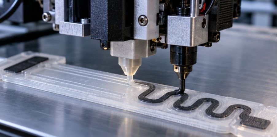
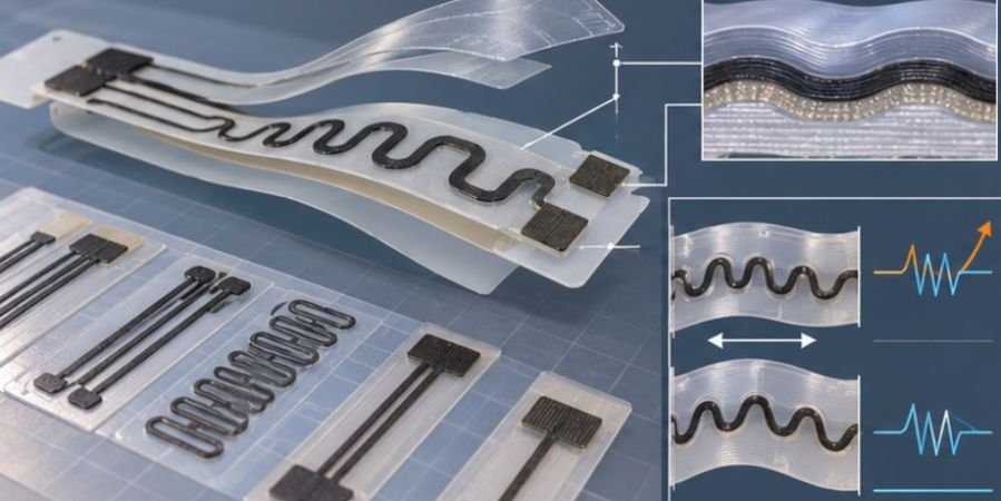
A straight conductive line works electrically, but it is rarely the best wearable sensor. Imagine printing a sensor across the knuckle of a robotic glove. A short straight trace experiences concentrated strain when the finger bends. Repeated movement can eventually create cracks or unstable resistance. A serpentine trace spreads deformation across a longer electrical path.
Start With a Flexible Base
Model a thin substrate that conforms to the body or robot. TPU is particularly useful for wearable prototypes because it can flex repeatedly without behaving like a rigid PLA plate.
For FDM prototypes, a practical starting structure might include:
- a flexible TPU base;
- a recessed conductive pathway;
- widened electrical contact pads;
- and a thin protective TPU layer over the trace.
If flexible filament has absorbed moisture, extrusion consistency can deteriorate. Before printing the sensor, learn how to dry 3D printer filament to help maintain consistent extrusion and improve print quality.
Use Serpentines or Auxetic Geometries
Serpentine traces stretch through geometry rather than forcing all strain into one section. Auxetic patterns offer another interesting option. Researchers at UC Davis have investigated 3D-printed conductive-filament structures integrated with textiles, including auxetic geometries designed for wearable stretch sensing.
Their testing found that printed structures could produce repeatable electrical responses during stretching cycles. That makes geometry almost as important as filament selection.
A Practical Printing Workflow
For anyone investigating how to 3d print conductive trace sensors for wearable robotics, this sequence provides a useful prototype process.
1. Print the Insulating Foundation
Print several TPU layers first.
The base should remain thin enough to bend comfortably but thick enough that the conductive path does not tear away from it.
2. Deposit the Conductive Path
Switch to the conductive material and print the sensor geometry.
Avoid extremely thin single-line traces during early prototypes. Wider paths are usually easier to manufacture consistently and less sensitive to minor extrusion defects.
3. Create Large Contact Pads
The electrical connection often fails before the actual sensing section.
Make the terminal pads substantially wider than the sensing trace. This gives you space for compression contacts, embedded wire, conductive adhesive, or another stable connection method.
Directly clamping an alligator clip onto a soft resistive trace can distort the material and change its resistance.
4. Encapsulate the Sensor
Add a thin insulating layer over the trace while leaving electrical terminals accessible.
Encapsulation protects the conductive network from abrasion, sweat, contamination, and accidental short circuits.
IEEE’s Flexible and Printed Sensors and Systems community identifies reliability, packaging, flexible materials, stretchable sensors, and system integration as major challenges in wearable and printed sensor development.
Measure Resistance Before Connecting a Microcontroller
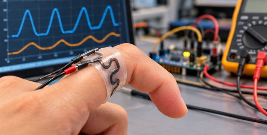
Do not immediately attach the sensor to an Arduino and start writing code. First characterize it with a multimeter.
Record resistance while the sensor is:
- relaxed;
- slightly bent;
- moderately bent;
- fully bent within its intended operating range;
- returned to its relaxed position.
Repeat the cycle 20–50 times.
You are looking for three things: a measurable resistance change, repeatability, and approximately the same baseline resistance after unloading.
A sensor that starts at 15 kΩ and returns to 15.5 kΩ may be workable. One that drifts from 15 kΩ to 25 kΩ after several bends probably needs redesigning.
For robotics, repeatability usually matters more than achieving the lowest possible resistance.
Calibrate the Sensor as a System
Once the trace behaves consistently, connect it through a voltage divider to an analog input. A simple resistive sensor can be interpreted from:
Vout = Vin × Rsensor / (Rfixed + Rsensor)
Choose the fixed resistor reasonably close to the sensor’s resistance near the middle of its useful range. That generally produces a larger measurable voltage change than using a dramatically mismatched resistor.
Next, collect readings at known joint angles.
For example:
0° → 2.1 V
30° → 2.4 V
60° → 2.9 V
90° → 3.5 V
You can then create a calibration curve relating voltage to joint position. A recent NIH-indexed study demonstrated a knee-worn sensor made from 3D-printed conductive TPU and used its electrical response to help distinguish activities including walking, running, sitting, and standing.
Common Problems and What They Mean
Resistance Jumps Randomly
Inspect the printed trace for gaps, inconsistent extrusion, damaged contacts, or cracked interfaces between materials.
The Sensor Works Once but Drifts
Conductive polymers can show hysteresis, where the resistance during unloading differs from resistance during loading.
Try reducing strain, changing trace geometry, allowing short recovery periods, or calibrating both movement directions separately.
The Trace Breaks Near the Connector
Increase the pad size and add strain relief. The transition between a rigid wire and flexible polymer is often the mechanically weakest point.
The Readings Change When the Wearer Moves Nearby
Capacitive coupling and electrical noise may be affecting the system. Shorter leads, shielding, filtering, stable grounding, and sensible signal conditioning can help.
Printed Sensors Are Not Printed Copper Wires
One misconception deserves special attention. Conductive filament is usually far more resistive than copper wire. That does not make it useless. It simply means its best role is often sensing rather than delivering substantial electrical power.
Flexible printed electronics is an active manufacturing field precisely because mechanical compliance introduces challenges that rigid electronics do not.
Beyond wearable robotics, additive manufacturing is also expanding the possibilities of engineering in extreme environments, including space missions where conventional manufacturing can be difficult. Discover how 3D printing is changing space exploration to learn how this technology supports innovative approaches to producing components beyond Earth.
Industry groups such as the Organic and Printed Electronics Association now track applications ranging from healthcare and IoT devices to flexible sensors and other printed systems.
Frequently Asked Questions
1. Can a normal 3D printer make conductive sensors?
Yes. An FDM printer can use conductive filament, although a dual-extrusion machine makes integrating conductive traces with insulating flexible material much easier.
2. Is conductive PLA or conductive TPU better?
Conductive TPU is generally preferable when the sensor must stretch or bend repeatedly. Conductive PLA is better suited to rigid or lightly flexing components.
3. Can printed traces replace copper wiring?
Usually not. Conductive filament has much higher electrical resistance than copper, making it better suited to sensing, touch detection, and low-current signal paths.
4. How do you waterproof a wearable printed sensor?
Encapsulate the conductive path inside flexible insulating polymer or a compatible protective coating while keeping durable electrical terminals available for connection.
Start With Repeatability, Not Complexity
The most impressive wearable sensor is not necessarily the one with microscopic traces, exotic ink, or the lowest resistance. It is the one that produces the same useful signal every time the wearer bends a joint.
Learning how to 3d print conductive trace sensors for wearable robotics therefore begins with material choice, but quickly becomes an exercise in mechanical design, electrical measurement, and calibration. Print a simple serpentine strain sensor, cycle it repeatedly, record its resistance, and redesign the geometry until the signal stabilizes. Once that foundation works, integrating it into gloves, braces, exoskeletons, and soft robots becomes far more practical.