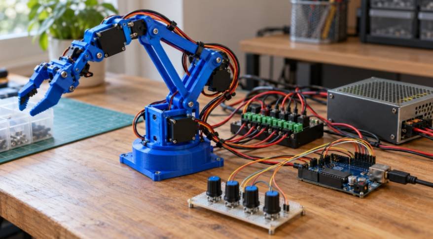
A robotic arm should move a foam block, not fight its own joints. My approach to a diy 3d printed robotic arm step by step starts with checking fit, power, and movement limits before attempting a pickup.
The EEZYbotARM MK2 provides a practical starting point. Its printed structure uses three main servos and a smaller gripper servo. That gives you base rotation, shoulder movement, elbow movement, and claw control—not four independently positioned wrist axes.
Gather Your Arduino Robotic Arm Components
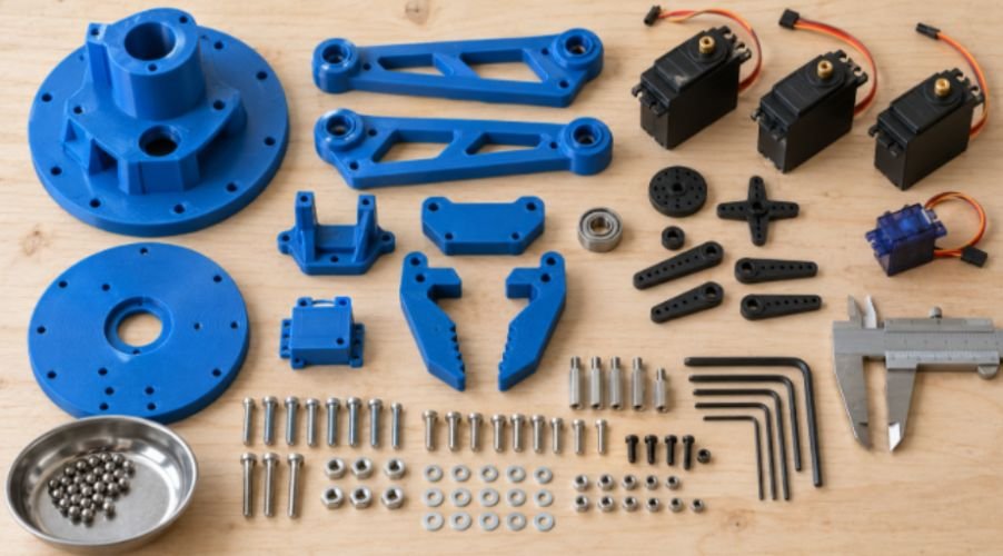
Start with the original EEZYbotARM MK2 assembly instructions and its matching parts list. Mixing files from different remixes can create mounting problems.
You need an Arduino Uno or Mega, three compatible standard positional servos, and an SG90-size gripper servo. Check the mounting dimensions and horn compatibility before substituting MG996R or MG90S models.
For the original design, buy the specified 606ZZ bearing and 6 mm steel balls. A 608ZZ bearing has different dimensions and requires a compatible redesign.
Gather the listed metric screws, nuts, washers, and threaded rods. American hardware stores may carry limited metric stock, so order the exact sizes together.
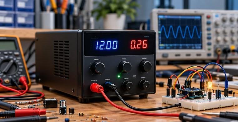
Add four 10kΩ potentiometers, hookup wire, suitable power terminals, and a regulated external servo supply. Choose its voltage and current capacity from your actual servos’ specifications.
Hex keys, calipers, a multimeter, and small files complete the bench setup. Keep your robotic arm project focused on lightweight objects first.
Step 1: Print and Check the Structural Parts
Print one servo bracket before committing to the entire set. Confirm that the servo fits without forcing the plastic apart.
My suggested starting profile uses a 0.2 mm layer height, four perimeters, and 30% infill. Treat these as starting settings, not a guaranteed structural specification.
PLA suits a cool indoor demonstration. PETG offers greater temperature resistance but may need more cleanup around mating surfaces.
Follow the designer’s part orientation. FFF prints have directional strength, so extra infill cannot compensate for poorly oriented layers. Prusa’s design guidance explains this relationship.
Remove supports and gently clean pivot holes. Enlarge only holes intended for clearance; preserve screw engagement elsewhere.
When choosing a 3d printer for beginner robotics projects, prioritize dimensional consistency over headline printing speed.
The same attention to print accuracy and mechanical fit is essential when designing a mobile robot. A guide on how to 3D print a robot chassis with Arduino explores the structural design considerations involved in building a printed chassis for Arduino-based robotics. Understanding component clearances, mounting points, and structural stability can help makers produce more reliable printed parts for both robotic arms and wheeled robots.
Step 2: Center the Servo Motors
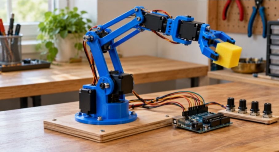
Center each servo before installing its horn.
Connect its signal to pin 9, power it externally, and join the supply ground to Arduino GND. Upload this sketch with the horn disconnected from the linkage:
#include <Servo.h>
Servo joint;
void setup() {
joint.write(90);
joint.attach(9);
}
void loop() {}
Once the shaft settles, disconnect power and fit the horn in the orientation specified by the assembly instructions.
A command of 90 represents the nominal midpoint. It does not guarantee a precisely measured physical angle across different servos.
Repeat for every motor. Avoid continuous-rotation servos: this project needs position control.
Step 3: Assemble the Base, Linkages, and Gripper
Install the bearing and steel balls according to your chosen base version. Fit the base servo and its gear without forcing their alignment.
Next, install the shoulder and elbow servos in their designated mounts. Connect the drive arms and parallel linkages.
Tighten pivot nuts enough to remove excessive play while preserving free movement. A joint that needs motor torque merely to overcome friction needs adjustment.
Assemble the gripper according to its specific linkage design. Do not assume every version uses interlocking gears.
Add thin foam or TPU gripping pads, keeping them clear of moving joints. Secure the base to a board or bench.
Route cables along the links with slack at each pivot. Keep loops away from gears and pinch points.
Step 4: Wire External Servo Power
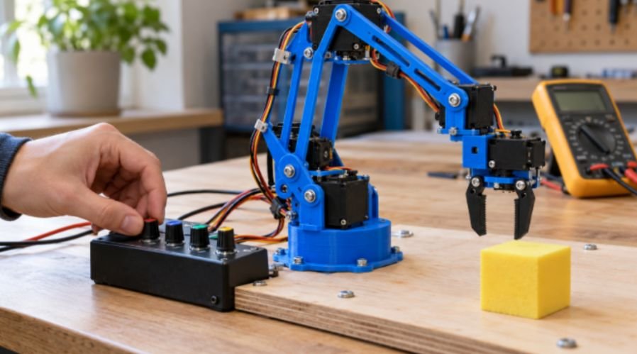
Connect base, shoulder, elbow, and gripper signals to digital pins 3, 5, 6, and 9.
With the Arduino Servo library on an Uno, these signals do not require hardware PWM pins.
Join servo positive wires to the external supply’s positive distribution terminal. Join their grounds to its negative terminal, then connect that terminal to Arduino GND.
Power the Arduino through USB. Keep the servo supply’s positive output separate from the Arduino 5V pin.
Adafruit’s servo hardware guidance recommends separate motor power and checking each servo’s permitted voltage.
Use wiring and terminals rated for the expected current. Avoid routing several high-torque servos through a solderless breadboard.
Connect each potentiometer’s outer terminals to Arduino 5V and GND. Connect its center terminal to A0, A1, A2, or A3.
Beyond robotic arms, microcontrollers can coordinate sensors and outputs to automate everyday tasks. A DIY smart plant watering system using ESP32 demonstrates how sensor inputs and programmed control can regulate watering based on plant conditions. Exploring this project provides another practical way to apply embedded programming, electrical connections, and automation principles beyond servo-driven robotics.
Step 5: Upload Four-Servo Arduino Control Code
This sketch moves commands gradually and keeps potentiometer control disabled until you send g through Serial Monitor.
The initial limits deliberately equal 90. Replace them only after checking each joint’s clearance. Arduino’s Servo library documentation describes the positioning functions used below.
#include <Servo.h>
Servo motor[4];
const byte signalPin[4] = {3, 5, 6, 9};
const byte potPin[4] = {A0, A1, A2, A3};
// Replace with individually verified joint limits.
const int lowAngle[4] = {90, 90, 90, 90};
const int highAngle[4] = {90, 90, 90, 90};
int position[4] = {90, 90, 90, 90};
bool enabled = false;
void setup() {
Serial.begin(9600);
for (byte i = 0; i < 4; i++) {
motor[i].write(position[i]);
motor[i].attach(signalPin[i]);
}
Serial.println(“Send g to enable potentiometers.”);
}
void loop() {
if (Serial.available()) {
char command = Serial.read();
if (command == ‘g’) enabled = true;
if (command == ‘s’) enabled = false;
}
if (!enabled) return;
for (byte i = 0; i < 4; i++) {
int target = map(analogRead(potPin[i]), 0, 1023,
lowAngle[i], highAngle[i]);
if (target > position[i]) position[i]++;
if (target < position[i]) position[i]–;
motor[i].write(position[i]);
}
delay(20);
}
Software slowing reduces abrupt commands; it does not detect collisions. Sending s freezes commands but leaves holding torque active.
Step 6: Calibrate Movement and Test Payload
Support the arm before powering it. Startup can still move a shaft toward its commanded position.
Expand one joint’s limits by a few degrees at a time. Keep other joints fixed. Stop before mechanical contact, sustained buzzing, or cable tension.
Individual limits cannot prevent every collision caused by combined shoulder and elbow positions. Test combinations slowly with an accessible servo-power switch.
For an original sizing example, consider a 50 g object held 15 cm horizontally from a joint. Its direct static torque contribution is:
0.05 kg × 9.81 m/s² × 0.15 m ≈ 0.074 N·m.
That excludes the arm’s weight, linkage geometry, friction, and acceleration. It is an illustration, not a payload rating.
Test an empty gripper first, then a foam block near the base. Increase reach before increasing weight.
If servos jitter, check grounding, supply voltage under load, and loose connections. If one joint buzzes, inspect binding and commanded limits before blaming the power supply.
Make Your Arm Behave Before Showing Off
I would choose ten smooth foam-block transfers over one dramatic lift. Repeatable movement shows that the mechanics, wiring, and calibration work together.
Your next step is simple: mark two nearby pickup positions and practice moving between them. Add record-and-playback control after manual operation becomes dependable.
Once a servo-driven robotic arm operates reliably, exploring other motor-control methods can broaden your understanding of robotics hardware. This guide on how to control a stepper motor with ESP32 and A4988 explains driver wiring, current-limit calculations, microstepping, and Arduino-compatible control code.
Comparing stepper motors with positional servos helps you understand which motion-control approach best suits a particular mechanism, positioning requirement, and robotics application.
Frequently Asked Questions
1. Can I build a diy 3d printed robotic arm step by step without CAD skills?
Yes; use an established model with matching assembly instructions and hardware.
2. Can an Arduino Uno control all four servos?
Yes; use the Servo library and a separate, correctly sized servo power supply.
3. How much weight can this printed arm lift?
There is no universal rating; servo quality, reach, linkage geometry, and print strength determine capacity.
4. Why does the arm move backward when I turn a knob?
Reverse that joint’s mapping endpoints after verifying its safe movement range.