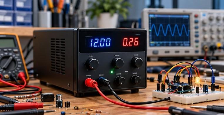
Digital logic can feel abstract when it is limited to symbols, equations, and truth tables. I find it becomes much easier to understand once students can flip a switch, watch an LED respond, and see exactly how a circuit makes a decision. That is what makes basic logic gate projects for students so effective.
Instead of only memorizing AND, OR, NOT, NAND, NOR, and XOR behavior, students can build working models that connect Boolean logic to real hardware. These projects can start with simple switches and LEDs, then progress to breadboards, 74-series ICs, binary adders, security circuits, water-level controllers, and traffic-light systems.
For U.S. classrooms, STEM clubs, science fairs, and introductory electronics labs, this hands-on progression creates a much stronger foundation in digital electronics.
What Should Students Learn Before Building Logic Gate Projects?
Logic gates make decisions using binary states represented as 0 and 1. An AND gate produces a HIGH output only when all required inputs are HIGH. An OR gate responds when one or more inputs are HIGH, while a NOT gate reverses its input.
NAND and NOR gates are particularly important because they are universal gates. XOR produces a HIGH output when two inputs differ, making it useful in comparison and binary arithmetic.
Students should also understand a truth table before moving into complex digital circuits. Testing every possible input combination against the expected output is one of the easiest ways to troubleshoot a breadboard.
Students can also strengthen their understanding of electronic inputs by exploring how a microcontroller reads continuously changing voltage levels. Unlike digital logic gates, which interpret signals as HIGH or LOW, a potentiometer can provide a variable analog voltage that a microcontroller measures and converts into a digital value. This guide on how to read a potentiometer with a microcontroller offers a useful next step for connecting basic digital logic concepts with practical electronics and sensor projects.
Beginner Project: How Can You Make Logic Gates With Only Switches?
I would start complete beginners with a mechanical logic board rather than an integrated circuit.
For an AND gate demonstration, connect two push buttons in series with an LED and a battery. Current reaches the LED only when both switches are closed. This physically demonstrates the condition A AND B.
For an OR gate, connect the two switches in parallel. Closing either pathway allows current to reach the LED.
A basic inverter-style demonstration can also illustrate NOT behavior, although students should carefully follow a proven low-voltage circuit rather than intentionally shorting a battery.
A cardboard or acrylic display board, low-voltage supply, switches, LEDs, and suitable resistors are enough to make a science-fair-friendly working model.
How Can Students Build AND, OR, and NOT Gates From Discrete Components?

The next step is diode-transistor logic.
Students can use small-signal diodes to explore simple AND and OR functions and an NPN transistor as an inverter for NOT logic. This type of project is especially useful when the goal is to understand what happens electrically inside digital logic instead of treating an IC as a black box.
It also connects digital electronics with semiconductor concepts such as current paths, transistor switching, input voltage, and output states.
Students should use a regulated low-voltage source and calculate appropriate resistor values rather than copying arbitrary component values from an unrelated circuit.
Which ICs Are Good for Beginner Breadboard Logic Projects?
Once students understand individual gates, I like moving to 74-series logic ICs. A typical educational setup may use a 7408 or 74HC08 for AND, a 7432 or 74HC32 for OR, a 7404 or 74HC04 for inversion, a 7400 for NAND, and a 7486 or 74HC86 for XOR.
Students can connect switches to inputs and LEDs to outputs, then work through every truth-table combination.
This stage also teaches practical skills such as reading IC pin diagrams, identifying VCC and ground, preventing floating inputs, organizing jumper wires, and diagnosing incorrect breadboard connections. Academic electronics labs commonly use this same progression to verify AND, OR, NOT, NAND, and NOR behavior.
How Can Students Build a Simple Logic Gate Security Alarm?
A simple security alarm introduces real-world combinational logic.
Two switches can represent a door sensor and a window sensor. OR logic causes an indicator or properly driven buzzer to activate if either sensor detects an open condition.
Students can make the circuit more interesting by adding an AND condition representing an ARM switch. Now the alarm responds to the sensors only when the system has been enabled.
This demonstrates how several Boolean conditions can work together inside a real control system.
Once students understand how logic gates process sensor inputs, they can explore how digital control signals operate external devices in practical automation projects.
For a useful next step, this guide on how to use a relay module with low-voltage control explains relay wiring, control signals, and the precautions needed when switching electrical loads.
It extends the lesson from Boolean decision-making to real-world electronic control while emphasizing appropriate driver circuitry and electrical safety.
How Does a Logic Gate Water Tank Controller Work?
A water tank controller is a strong intermediate project because it introduces automation.
Two low-voltage sensor inputs can represent LOW and FULL water levels. Students can then design NAND or AND/NOT logic to determine when a simulated pump indicator should switch on and when it should stop.
For classroom safety, I recommend using LEDs to represent the pump first. A logic IC should not directly power a household water pump or other high-current load. Real loads require appropriate switching and protection circuitry.
The important lesson is the decision process: multiple sensor conditions produce one controlled output.
How Can Students Make a Four-Switch Digital Combination Lock?

A digital combination lock makes Boolean expressions easy to understand.
Suppose four switches represent A, B, C, and D, and the correct code is 1-0-1-0. Inputs A and C need to be HIGH, while B and D need to be LOW.
The LOW requirements can pass through NOT gates before the signals are combined with AND logic. Only the correct combination produces the unlock output.
Students can display the result using a green LED. This creates a practical lesson in combinational logic, inversion, Boolean expressions, and digital security principles.
Why Are NAND, NOR, and XOR Projects Worth Building?
After students understand the basic gates, NAND and NOR experiments demonstrate something powerful: either gate type can be combined to reproduce other Boolean functions.
An XOR circuit provides another useful challenge. With two switches as inputs, the output LED turns on when the input states are different.
Students can first construct XOR from combinations of simpler gates and then compare the result with a dedicated XOR IC. This reinforces the connection between Boolean algebra and physical hardware. Breadboard teaching projects frequently use exactly this truth-table verification approach.
How Do You Build a Half-Adder and Full-Adder With Logic Gates?
A half-adder is where students begin seeing how computers perform arithmetic.
It accepts two binary inputs. An XOR gate creates the SUM output, while an AND gate generates CARRY. When the inputs are 1 and 1, the binary result is 10, meaning SUM is 0 and CARRY is 1.
A full-adder expands the idea by adding a third input called carry-in. Students can construct one using interconnected logic gates or by combining half-adder stages. The circuit produces SUM and CARRY outputs for all eight possible three-input combinations.
This is one of the strongest ways to connect Boolean logic with computer architecture.
Can Students Build a Majority Voting Circuit?
A three-input majority circuit produces HIGH when at least two of its three inputs are HIGH.
Students can design the required Boolean expression using combinations of AND and OR gates and then test all eight input combinations.
Unlike a single-gate demonstration, this project requires students to convert a verbal requirement into a logical circuit. That makes it excellent preparation for digital design and introductory computer engineering.
How Can Logic Gates Control a Model Traffic Light?
A traffic-light project combines logic with automation.
Students can use switches or low-voltage sensors to represent vehicles on a main road and side road. AND, OR, and NOT conditions then determine which model LEDs should illuminate.
A simple design might prioritize the main road until a vehicle is detected on the side road. Students can expand the project by introducing additional conditions, although realistic traffic timing eventually requires sequential logic, clocks, or a microcontroller.
The project demonstrates how digital systems interpret sensors and make decisions.
When students extend logic gate experiments into motorized models or robotics projects, electrical noise becomes an important practical consideration.
Brushed DC motors can introduce interference that disrupts sensor readings or resets a microcontroller, so understanding why a DC motor causes electrical noise helps students recognize the importance of noise suppression, stable power supplies, and reliable signal connections in digital control systems.
What Is the Best Order for Learning Logic Gate Projects?

I recommend moving from physical switches to discrete semiconductor logic, then to individual IC gates, combinational circuits, arithmetic circuits, and finally automation projects.
Students should predict the result before switching power on, record each truth table, and troubleshoot one stage at a time.
That process matters as much as getting the final LED to illuminate because digital electronics is ultimately about understanding why an output occurred.
Frequently Asked Questions
1. What are the best basic logic gate projects for students?
Good choices include switch-based AND and OR models, diode-transistor gates, LED truth-table circuits, security alarms, combination locks, water-level controllers, half-adders, full-adders, voting circuits, and model traffic controls.
2. What are the seven basic logic gates?
The seven commonly taught gates are AND, OR, NOT, NAND, NOR, XOR, and XNOR.
3. Which logic gates should a beginner learn first?
I recommend starting with AND, OR, and NOT because they make the basic rules of Boolean logic easy to visualize. NAND, NOR, and XOR can follow once students understand truth tables.
4. Can a logic gate directly operate a motor or relay?
Usually, a logic output should not directly drive a high-current load. A properly designed transistor, MOSFET, relay driver, or similar interface may be required depending on the load and logic family.
Final Thoughts
I find that logic gates become much easier when students stop treating them as symbols on a worksheet and begin treating them as physical decision-making circuits.
A pair of switches can demonstrate Boolean logic. A few ICs can create a digital lock. XOR and AND gates can perform binary addition. Add sensors and the same principles can control alarms, tank-level indicators, or traffic simulations.
The goal is not to build the most complicated circuit possible. It is to understand each input, predict the output, verify it with a truth table, and explain why the circuit behaves that way. That foundation prepares students for robotics, computer engineering, embedded systems, and more advanced digital electronics.