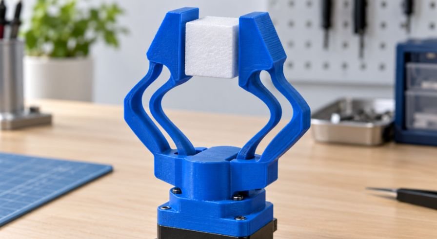
A robotic gripper that bends once proves very little. The useful question is whether it returns accurately after repeated movements.
My approach to how to print compliant mechanisms for robotics starts with the required motion, then works backward through hinge geometry, filament, and toolpaths. A stronger filament cannot rescue a hinge that concentrates strain at one sharp corner.
Compliant mechanisms replace some conventional joints with flexible sections. BYU’s introduction to compliant mechanisms explains how this approach can reduce parts and joints. The tradeoff is that the structure must carry loads while bending.
Define the Motion Before Designing the Hinge
Before opening the slicer, I would write down four requirements: travel, force, available space, and expected cycles.
A gripper opening 15 degrees needs a different flexure from a joint rotating 45 degrees. Include the payload and actuator forces, not just unloaded movement.
Also decide whether the mechanism stays bent. Sustained deflection introduces creep and stress relaxation, which can change positioning or gripping force.
Add mechanical stops to limit travel. Position them so actuator overrun transfers into rigid structures rather than stretching the hinge farther.
When you 3d print a robot chassis, provide mounting surfaces that support the flexure without twisting its base.
Choose Filament for Repeated Flexing
PETG is a practical starting material for accessible prototypes. However, a successful demonstration does not establish its service life.
Unfilled nylon can suit tougher functional flexures. Its properties depend on grade, moisture, and processing. Dry the filament according to its manufacturer’s instructions, then test parts under representative operating conditions.
Polypropylene deserves consideration for living hinges. UltiMaker’s flexible-material guidance identifies PP’s fatigue resistance and hinge applications. That does not guarantee millions of cycles from a particular FDM print.
PLA can verify geometry and demonstrate low-strain movement. I would avoid assuming it will survive repeated large bends or warm operating conditions.
ABS and ASA offer useful heat resistance, but neither eliminates creep. TPU suits soft grippers, although its flexibility can reduce positioning stiffness.
For material comparisons, use printed-part data where available. Formlabs’ material-selection guide explains why manufacturing process and directional properties affect performance.
Calculate Flexure Hinge Thickness and Length
The calculation behind how to print compliant mechanisms for robotics begins with strain, rather than infill percentage.
For a uniform rectangular beam under an end moment, approximate surface strain as:
t2L
With linear elastic behavior:
Et2L
Here, t is bending thickness, L is flexible length, and E is Young’s modulus. Convert degrees to radians using =/180.
Using yield strength Sy and safety factor n:
LEtn2Sy
This is a preliminary yield check. End forces, restricted motion, and root geometry can produce different stress distributions. Complex mechanisms need more detailed analysis.
Worked Example: A 45-Degree PA12 Hinge
Assume illustrative PA12 properties of E=1,400 MPa and Sy=45 MPa. These are calculation inputs, not universal filament specifications.
For t=0.8 mm, =0.785 radians, and n=2:
L1400(0.8)(0.785)(2)2(45)19.54mm
At L=20 mm, predicted surface strain is approximately 1.57%, and stress is 21.98 MPa.
That passes the assumed yield check. It does not establish fatigue life.
For a 10 mm hinge width, the ideal end moment is:
M=Ebt312L23.4N·mm
Use this to begin estimating actuator demand. Include linkage geometry, friction, and payload forces before selecting a motor.
Why Small Thickness Errors Matter
Here is the most useful sensitivity check: bending stiffness scales with thickness cubed.
Increasing thickness from 0.8 to 0.9 mm increases ideal stiffness by approximately 42%, with everything else unchanged. At a fixed rotation, surface strain also rises by 12.5%.
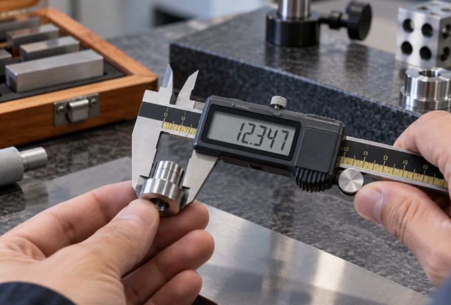
Measure the printed hinge, rather than trusting the CAD dimension. First-layer swelling or excess flow can noticeably change actuator demand.
Increase width when you need more bending stiffness without increasing ideal pure-bending strain. Check lateral stability separately; width alone does not guarantee a stable joint.
Set Print Orientation and Slicer Paths
For a planar mechanism that bends within its own plane, printing flat often places the beam length within each layer.
The aim is to carry longitudinal tension through continuous deposited roads while avoiding layer separation. “Parallel to layer lines” alone is too vague to define a reliable orientation.
Use generous fillets where flexible beams meet rigid blocks. Keep support contact and rough surfaces away from highly strained regions.
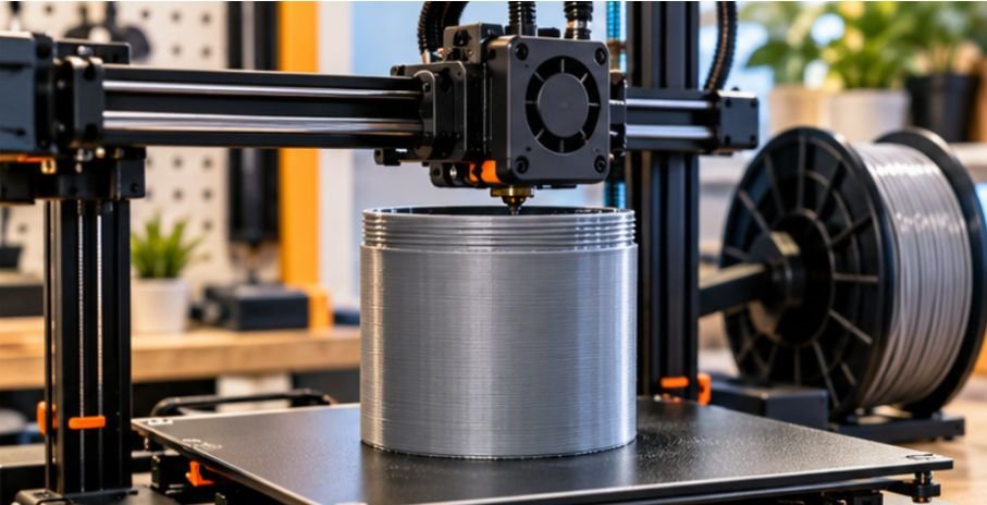
Before production, calibrate a 3d printer for functional mechanical parts, especially extrusion flow and dimensional accuracy.
Make the Toolpath Continuous
A 0.4 mm nozzle with approximately 0.4 mm extrusion width makes a nominal 0.8 mm hinge a reasonable trial. Two extrusion widths are a starting target, not a dimensional guarantee.
Inspect every hinge layer in the preview. Look for uninterrupted paths, voids, short segments, and seams near beam roots.
Do not automatically disable Arachne. Prusa’s documentation explains that variable-width paths can reduce gap fill. Compare both generators and choose the cleaner toolpath for your geometry.
Move seams into rigid regions where possible. Start with the manufacturer’s material profile; tune temperature, speed, and cooling using coupons rather than universal settings.
Print, Cool, and Test Your Mechanism
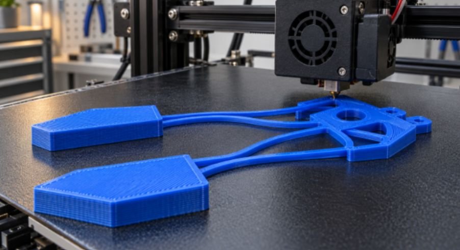
Print a separate hinge coupon before committing to the complete robot. If you’re planning a larger build, this DIY 3D-printed robotic arm project offers a related project to explore alongside your flexure testing.
Let it reach room temperature before loading. This avoids judging a still-warm part; it does not mean every polymer must crystallize.
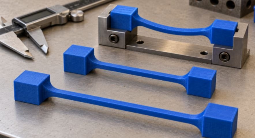
My suggested comparison uses three beam lengths with identical measured thickness. Test each through the intended travel using the same fixture.
Record unloaded return position, force at a fixed displacement, and visible damage. Check again after repeated cycles and a representative hold period.
Initial checks at 10, 100, and 1,000 cycles can expose early problems. Qualification must reflect the required service life and actual loads.
For bistable grippers, measure snap-through force and retained grip separately. Two stable positions do not automatically provide secure payload retention.
Troubleshoot Robotic Flexure Failures
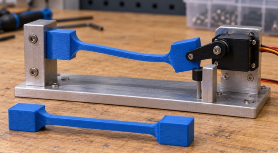
Root cracks suggest concentrated strain: increase the radius, lengthen the beam, or reduce travel.
Splitting between layers calls for reviewing orientation, filament condition, and bonding settings.
Permanent bending can indicate excessive strain, heat, creep, or a combination. Reduce deflection and test the intended hold time.
Unexpected actuator load deserves a thickness measurement first. If the joint wobbles sideways, consider paired flexures or a guided arrangement.
Give Your Robot Some Flex—Without the Snap
My preferred next step is a small coupon with a measured thickness and controlled travel stop. It makes the design easier to evaluate before motors and payloads complicate testing.
The strongest approach to how to print compliant mechanisms for robotics combines calculations with repeatable measurements. Give the hinge enough length, inspect its toolpaths, and make it earn its place in the robot.
Frequently Asked Questions
1. What is the best filament for a 3D-printed robotic flexure?
Unfilled nylon and polypropylene are useful candidates; choose through testing for your required motion, environment, and life.
2. Can I print compliant mechanisms with a 0.4 mm nozzle?
Yes; verify that the slicer produces continuous paths and measure the resulting hinge thickness.
3. How thin should a 3D-printed flexure hinge be?
Choose thickness from printable geometry, allowable strain, required stiffness, and tests—not one universal minimum.
4. Does 100% infill prevent compliant hinges from breaking?
No; geometry, toolpaths, material condition, and loading remain critical.