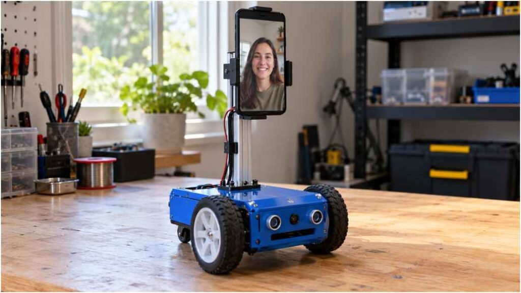
A video call cannot turn toward someone across the room, but a robot carrying that call can. For a DIY telepresence robot project, I would start with a spare smartphone, an ESP32, and a stable wheeled base. That keeps the first milestone clear: see, speak, steer, and stop reliably.
My approach separates the video call from the drive system. You can then troubleshoot a frozen camera without blaming motor wiring. Below, I explain the hardware, power, software, and tests needed for a practical indoor prototype.
Choose Your Wi-Fi Robot Architecture
The first decision in a DIY telepresence robot project is where video processing happens. Both approaches need a screen, camera, microphone, speaker, and motor controller.
ESP32 and a Repurposed Smartphone
For my DIY telepresence robot project, I prefer a phone-first prototype because the phone already combines those communication parts. Mount it securely and run a video call. Let the ESP32 receive drive commands through Wi-Fi and operate the motor driver.
The video app does not automatically control the wheels. You still need ESP32 firmware and a separate browser dashboard. Initially, keep both the operator and robot on the same local network.
Raspberry Pi Telepresence Robot
A Pi-based DIY telepresence robot project gives you more control over the interface and camera pipeline. However, you must add a display, microphone, speaker, storage, and suitable power.
A Pi camera provides outgoing vision; it does not display the caller or supply two-way audio. Raspberry Pi recommends a 5V/3A supply for the Pi 4 in its getting-started documentation. Budget connected accessories separately.
I would choose the Pi route for software integration, rather than assuming it guarantees better video performance.
Budget Your Parts Before Buying
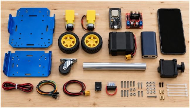
I would budget a DIY telepresence robot project in dollars using local supplier quotes. The supplied rupee estimates are useful planning references, but they are not verified US retail prices.
Here is my illustrative phone-build allowance, not a live shopping quote:
| Item | Planning allowance |
| Two-wheel chassis with motors | $25 |
| ESP32 development board | $10 |
| Suitable motor-driver board | $10 |
| Motor battery pack and charger | $25 |
| USB power bank | $20 |
| Phone clamp and short mast | $15 |
| Switch, fuse, wiring, fasteners | $15 |
| Subtotal with an existing phone | $120 |
I would add a $25 contingency, bringing this example to $145 before tax and shipping. Check whether a chassis includes motors before buying them twice. Add any phone replacement, tools, or fabrication costs separately.
Build a Mobile Robot Base That Stays Upright
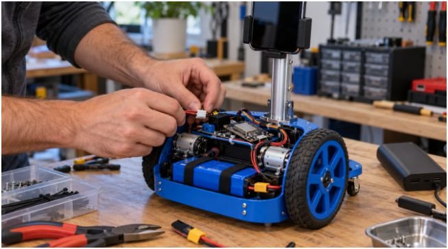
A DIY telepresence robot project needs stability more than height. Start with two geared wheels and a caster, then place batteries low and centrally.
I would test a short phone mount before adding a three-foot mast. A tall screen increases tipping risk during turns or when a wheel catches a rug. A small hobby chassis may lack sufficient payload capacity.
Use a rigid clamp, strain relief, and accessible power switch. Keep cables clear of wheels. Test with the full mounted load and gentle acceleration before driving near furniture.
If you enjoy gait mechanics, a bipedal walking robot offers a separate learning path. For telepresence, wheels make camera stability and control simpler.
Wire the Motor Driver and Battery Supply
Power faults can derail a DIY telepresence robot project before the software runs. Match battery voltage to the motors, and select a driver that handles their stall current.
An L298N can work, but its voltage losses make it less attractive for small, low-voltage motors. Consider a compatible modern driver. Texas Instruments’ DRV8833 documentation explains voltage limits and package-dependent current ratings; a module’s cooling also affects usable current.
For an ESP32 with a compatible DRV8833 breakout, a starting connection map is:
| Connection | Destination |
| Motor-pack positive through fuse and switch | Driver VM |
| Motor-pack negative | Driver GND |
| ESP32 GND | Driver GND |
| ESP32 GPIO 25/26 | Driver AIN1/AIN2 |
| ESP32 GPIO 27/33 | Driver BIN1/BIN2 |
| Driver AOUT1/AOUT2 | Left motor |
| Driver BOUT1/BOUT2 | Right motor |
| Regulated USB power | ESP32 development-board USB input |
Check your exact board pinout and sleep-pin requirements. This map does not apply unchanged to an L298N.
Use separate motor and logic power branches, with a shared control ground. Never connect battery voltage to GPIO. Espressif’s ESP32 datasheet specifies its electrical limits.
A two-cell lithium pack reaches 8.4V when fully charged. Do not assume nominal 7.4V suits every TT motor. Use a protected assembled pack and matching charger. Optional servos need their own adequately rated regulated supply.
Connect WebRTC Video and Remote Robot Control
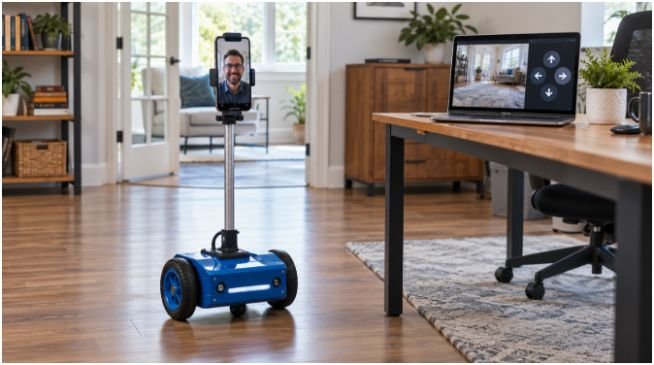
For a DIY telepresence robot project, I would establish a working video call before enabling motion. Check camera framing, speaker volume, and echo while the motors remain disabled.
Give your DIY telepresence robot project a browser dashboard with forward, reverse, turn, and stop controls. Send bounded speed commands over WebSockets. For differential drive, forward runs both motors together; turning changes their relative speeds.
Send commands only while a control remains pressed. Stop on release, lost connection, or stale commands. A 300–500ms firmware timeout is a starting design choice that requires testing.
Internet operation adds another layer. A local ESP32 dashboard is not automatically accessible from another building. Use an authenticated VPN or secured relay for control, rather than exposing an unauthenticated motor endpoint.
WebRTC’s TURN-server guidance explains why media connections may need a relay across networks. A successful video call does not prove the drive channel works remotely.
A Gesture controlled robot can inspire later hand-motion controls. I would retain a visible stop button and connection timeout with any input method.
Test Latency, Stopping Distance, and Runtime
My first acceptance test for a DIY telepresence robot project would be disconnection behavior. Raise the wheels, command motion, and interrupt Wi-Fi. Confirm that firmware stops the motors without receiving another message.
Then test at low speed on a clear floor. Measure video delay and stopping travel with a helper beside the cutoff switch.
Here is a worked design example: at 0.25 meters per second, a 0.4-second video delay hides 0.10 meters of travel. Adding a 0.3-second operator reaction and 0.15-second braking interval yields roughly 0.21 meters. This simplified estimate assumes speed stays constant during braking; actual results need measurement.
Keep clearance beyond that estimate. A command timeout cannot detect an obstacle or a frozen video feed while commands still arrive.
Finally, log your DIY telepresence robot project battery runtime under real calling and driving conditions. Check for resets, hot drivers, audio dropouts, and power banks that switch off unexpectedly.
Give Your Video Call Wheels, Not an Attitude
I would call a DIY telepresence robot project successful when it holds a clear conversation and stops predictably. Fancy camera motion can wait.
Start with the phone-based architecture, a short mount, and local Wi-Fi. Your next step is to validate motor power and the disconnect timeout with the wheels raised. Earn dependable movement before adding height or internet access.
Frequently Asked Questions
1. Can I build a DIY telepresence robot project with an old phone?
Yes; use the phone for video and audio, plus an ESP32 and motor driver for movement.
2. Do I need a Raspberry Pi for a telepresence robot?
No; a phone handles communication, while a Pi suits builds requiring deeper software integration.
3. Can I control a homemade telepresence robot over the internet?
Yes, with authenticated remote control and a video service or WebRTC setup that works across networks.
4. How do I stop a Wi-Fi robot when its connection fails?
Implement a firmware command timeout, stop on disconnect, and provide an accessible physical cutoff switch.