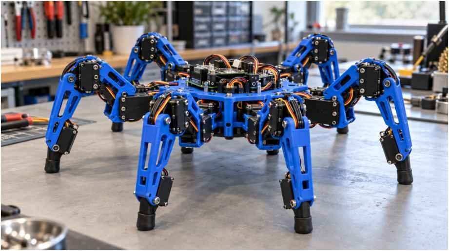
Building a DIY hexapod spider robot tests every discipline of maker robotics at once. When my first prototype finally stood up, it immediately collapsed because eighteen budget servos tried to pull twelve amps through a thin printed trace.
Getting six multi-jointed legs to traverse rough terrain requires more than just bolting plastic limbs to a chassis. You need robust power planes, clean bus wiring, and geometric math running on a capable microcontroller.
I spent months refining this build to eliminate jitter, brownouts, and unnatural movements. This breakdown shares the exact engineering decisions, electrical topologies, and kinematic pipelines that make an 18 Degrees of Freedom (18DOF) hexapod walk with rock-solid stability.
Essential Hardware and Power Delivery Architecture
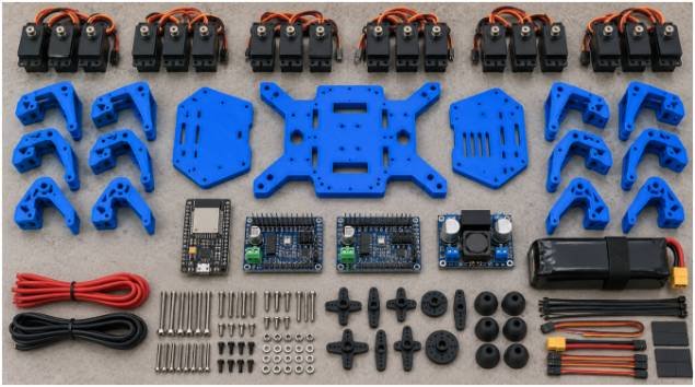
An 18DOF hexapod relies on eighteen independent actuators. Each leg features three critical joints: the coxa (hip pan), femur (thigh lift), and tibia (shin reach). Controlling this array demands a hardware pipeline that prevents CPU bottlenecks and electrical noise.
+————————————————————-+
| ESP32 Microcontroller Brain |
| (Inverse Kinematics, Gait Sequencing) |
+——————————+——————————+
|
I2C Bus (SDA / SCL)
|
+——————–+——————–+
| |
+———v———-+ +———-v———+
| PCA9685 Driver #1 | | PCA9685 Driver #2 |
| (Legs 1-3: Servos) | | (Legs 4-6: Servos) |
+———+———-+ +———-+———+
| (PWM Signals Only) | (PWM Signals Only)
| |
+———v—————————————–v———+
| 18x MG996R / MG90S Metal Servos |
+——————————^——————————+
|
Regulated 5.5V High-Amp Bus
|
+——————————+——————————+
| High-Current Buck Converter (15A Peak / 10A Cont.) |
+——————————^——————————+
|
2S or 3S LiPo Battery (7.4V – 11.1V)
Controller Selection and PWM Driver Integration
Generating eighteen distinct pulse-width modulation (PWM) signals directly from a standard microcontroller core wastes valuable clock cycles. I use an Espressif ESP32 as the central brain. Its dual-core architecture allows one core to compute continuous inverse kinematics while the second core handles telemetry and input signals.
To run the servos, offload timing tasks to two 16-channel Adafruit PCA9685 PWM drivers communicating over I2C. Daisy-chaining these boards requires tying their ground planes together and assigning unique I2C addresses via solder jumpers. This keeps the processor free to calculate smooth joint trajectories.
Taming the 12-Amp Servo Current Spikes
Power distribution causes the majority of hexapod build failures. A common digital micro servo like the MG90S draws roughly 700mA at stall. Full-sized metal-gear MG996R servos draw up to 1.5A under heavy mechanical load. During an aggressive tripod stance switch, six to nine servos engage simultaneously. That generates dynamic loads between 8A and 12A.
Standard linear voltage regulators fail instantly under these loads. Running them triggers thermal throttling or drops your system logic voltage low enough to force a brownout reset.
Power your robot using a dedicated 2S or 3S LiPo battery wired to a heavy-duty step-down buck converter. The converter must deliver at least 10A continuously and 15A during peaks.
Always isolate your power rails. Feed logic power to the ESP32 through a filtered 5V rail, and route motor power directly to the driver terminals. Documented tests on Pololu power delivery systems confirm that shared, unbuffered logic-and-servo rails introduce voltage ripples exceeding 1.2V. That level of noise corrupts digital logic states. Place a 1000µF low-ESR electrolytic capacitor across every power input terminal on your servo boards to suppress transient inductive spikes.
Mechanical Assembly and Leg Geometry Calibration
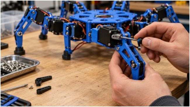
The mechanical foundation must resist lateral flex. I 3D print all structural components using PETG or ABS instead of standard PLA. PETG withstands outdoor thermal exposure and flexes slightly without snapping when a leg strikes an obstacle.
Zeroing Servos Before Structural Assembly
Never attach a servo horn to an uncalibrated motor. Mount each servo electrically to your driver, flash a calibration sketch, and send an exact 1500-microsecond neutral command (90 degrees).
Only assemble the coxa, femur, and tibia brackets after each motor holds this neutral center. Aligning horns visually while the motor is unpowered leaves your joints offset by 5 to 15 degrees. That introduces mechanical binding and asymmetric travel ranges right out of the gate.
Joint Placement for Optimum Static Stability
A hexapod relies on maintaining an active center of mass (CoM) within the polygon formed by its grounded feet. Keep the coxa rotation axis perpendicular to the ground plane, with femur and tibia hinge pins parallel to each other.
Adding an 8mm silicone or soft rubber tip to each tibia end point provides essential mechanical dampening. Hard plastic tips slip across smooth surfaces, which introduces tracking drift into your coordinate equations.
[Coxa Joint] (Yaw / Horizontal Panning)
|
+==== [Femur Joint] (Pitch / Vertical Lift)
\
\ Femur Link (L1)
\
[Tibia Joint] (Pitch / Reach)
|
| Tibia Link (L2)
|
(Foot) <– High-grip rubber contact point
Mastering 3D Inverse Kinematics and Walking Gaits
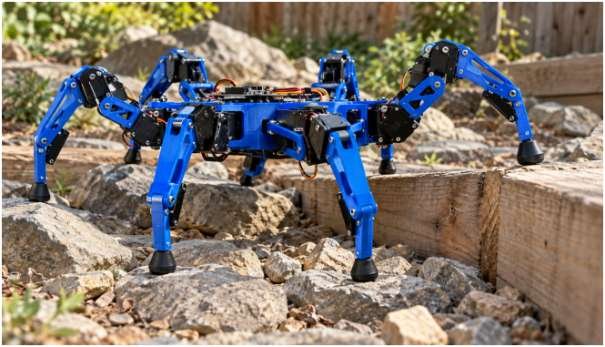
Manual joint angle programming produces robotic, jerky movements. Fluid spider-like locomotion requires Inverse Kinematics (IK). You define where each foot belongs in 3D Cartesian space (X,Y,Z) relative to the hip mount, and your code derives the exact servo angles automatically.
Translating Cartesian Coordinates to Joint Angles
The kinematics pipeline splits into two geometric stages: a top-down horizontal projection for the hip, followed by planar two-link trigonometry for the thigh and shin.
First, calculate the horizontal coxa angle (c):
c=atan2(Y,X)
Next, find the true radial distance (R) from the coxa pivot to the foot target, subtracting the mechanical length of the coxa bracket (Lc):
R=X2+Y2–Lc
Now solve the vertical planar triangle formed by the femur length (L1), tibia length (L2), horizontal projection (R), and vertical height (Z). Using the planar Euclidean distance:
D=R2+Z2
Apply the Law of Cosines to calculate the internal knee angle between the femur and tibia (knee):
(knee)=L12+L22–D22L1L2
Using these equations, updating the target coordinates shifts all three leg joints smoothly without manual angle mapping.
Tripod vs. Wave Gait Implementation
Locomotion gaits define how your robot sequences leg movement. Choosing the right gait depends on your terrain and speed requirements.
Tripod Gait (50% Duty Factor):
Group A: [L1] [R2] [L3] –> SWING PHASE (In air)
Group B: [R1] [L2] [R3] –> STANCE PHASE (Grounded)
Wave Gait (83% Duty Factor):
Leg Sequence: [L3] -> [L2] -> [L1] -> [R3] -> [R2] -> [R1]
(5 legs stay planted while 1 leg steps forward)
The Tripod Gait offers the fastest translation on level floors. The legs divide into two alternating groups of three: Group A (Front-Left, Middle-Right, Back-Left) and Group B (Front-Right, Middle-Left, Back-Right). While Group A lifts and pushes forward, Group B stays planted to drive the chassis ahead.
This configuration maintains a continuous Self-balancing triangular platform. However, it requires broad, flat surfaces.
The Wave Gait delivers unmatched rough-terrain capability. Only one leg lifts at a time, moving sequentially from back to front along the body. Five feet remain anchored to the ground continuously.
This creates a broad pentagonal stance. Research cataloged in IEEE Xplore leg locomotion studies reveals that wave gaits provide up to three times the static stability margin of a tripod gait on uneven surfaces, eliminating tipping risks across loose rock or inclines.
| Performance Metric | Tripod Gait | Ripple Gait | Wave Gait |
| Grounded Legs | 3 of 6 (50%) | 4 of 6 (~67%) | 5 of 6 (~83%) |
| Gait Duty Factor | =0.50 | =0.67 | =0.83 |
| Speed Index | High (1.0x) | Moderate (0.6x) | Low (0.25x) |
| Static Stability Margin | Minimal (Triangular) | Robust (Trapezoidal) | Maximum (Pentagonal) |
| Terrain Profile | Polished flat surfaces | Low carpet, slight bumps | Broken rocks, steep inclines |
Integrating Autonomous Sensors and Environmental Navigation
A hexapod truly comes to life when you free it from tethered remote controls. Mounting a micro time-of-flight (ToF) distance sensor or ultrasonic transducer to a panning coxa servo creates an active Obstacle avoiding scanning system.
Connect an MPU-6050 six-axis Inertial Measurement Unit (IMU) to the main chassis plate along the central axis of symmetry. By reading pitch and roll angles through an onboard complementary filter, you can dynamically adjust individual leg heights.
If the robot steps onto an uneven ledge, the downhill legs extend automatically while the uphill legs retract, keeping the payload deck completely level.
Frequently Asked Questions About Building Hexapods
1. What causes severe servo jitter in a DIY hexapod spider robot?
Jitter stems from shared-rail ground bounce, low battery voltage, or using low-cost servos with deadbands under four microseconds.
2. Can an Arduino Uno control an 18DOF hexapod?
An Arduino Uno lacks the RAM and processing bandwidth needed for simultaneous 18-channel inverse kinematics and gait planning.
3. What battery works best for an 18-servo hexapod?
A high-discharge 2S LiPo battery (7.4V, 2200mAh or higher, rated at 25C minimum) paired with a 10A buck converter provides ideal power.
4. Why are metal-gear servos necessary for hexapod legs?
Plastic gear teeth quickly strip under the high torque spikes created when a leg strikes solid ground.
Deploy and Calibrate
Start by constructing a single leg on your workbench. Connect it to your driver board and verify your inverse kinematics library calculations before assembling the entire robot. Once you calibrate mechanical endpoints, confirm your buck converter maintains steady voltage under load, and verify your coordinate systems, your hexapod will be ready to tackle real-world terrain.