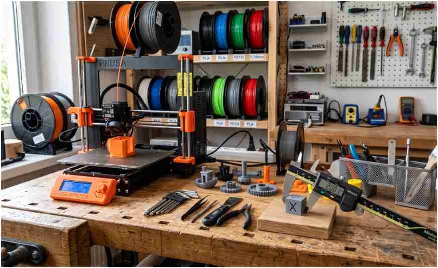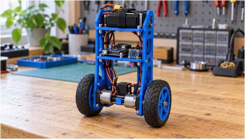
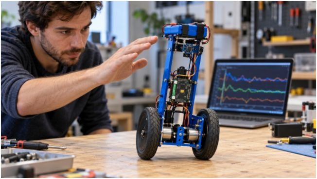
Few workbench milestones feel as rewarding as watching a two-wheeled machine resist gravity on its own. A self-balancing robot DIY build forces you to tackle hardware limitations, sensor drift, and closed-loop control all at once. During my first build, I watched an Arduino Nano oscillate violently before flipping into my workbench wall. The culprit was not broken code. It was a failure to account for motor deadband and loop cycle timing.
Building a functional inverted pendulum requires understanding the physical system before writing code. When you balance a broomstick on your palm, your eyes track the broom’s tilt. Your brain calculates how fast it is tipping, and your hand darts in that direction to keep the center of mass over the pivot point. Your robot works on the exact same principle.
The Physics Behind Dynamic Upright Equilibrium
An upright two-wheeled bot is inherently unstable. Without constant motor correction, gravity pulls the top mass downward, generating an accelerating rotational torque.
Mathematical Model of the Inverted Pendulum
The chassis rotates around its wheel axles along angle . The equation governing rotational acceleration balances gravitational torque against wheel acceleration:
Id2dt2=mgL()-FL()
Where:
- I represents the body’s moment of inertia.
- m is the chassis mass above the wheels.
- g is the acceleration due to gravity (9.81m/s2).
- L is the distance from axle to the center of mass.
- F is the horizontal corrective force supplied by the drive wheels.
For small deviations around balance point zero, we approximate () and ()1. This reveals a core engineering rule: raising your center of mass (L) increases inertia and slows down the tipping frequency. A taller chassis gives your control loop more milliseconds to react before the angle exceeds recovery limits.
[ Battery / Electronics ] <– High Center of Mass (CoM)
|
| Distance L
|
[Axle / Motors] <– Pivot Point
O O
Core Hardware Selection and Mechanical Balance
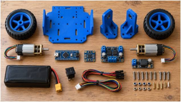
Reliable closed-loop control requires choosing components with fast response times and low electrical noise.
Microcontroller and IMU Fusion
An ATmega328P on an Arduino Uno or Nano handles basic floating-point math, though an ESP32 offers faster clock speeds and built-in hardware timers. For state sensing, the MPU6050 remains the hobby standard. It houses a 3-axis accelerometer and a 3-axis rate gyroscope on a single silicon die.
Accelerometers read gravity vectors accurately when stationary, but wheel vibrations corrupt their readings. Gyroscopes track rapid rotational changes without vibration noise, yet their output drifts over time due to numerical integration bias. Combining both sensors through a fusion algorithm yields clean, lag-free tilt angles. Refer to Arduino Documentation for proper I²C pinouts on your board.
Drive System Showdown: Stepper vs. Geared DC Motors
Your choice of actuators dictates your software strategy:
- NEMA 17 Steppers: Paired with silent TMC2208 drivers, steppers eliminate gearbox backlash entirely. They respond immediately to step pulses. However, they pull full holding current continuously, exhausting small battery packs within fifteen minutes.
- Geared DC Motors with Encoders: Motors like the GB37-520 draw power dynamically, staying cool during long operation. Yet standard spur gearboxes exhibit 1 to 3 of mechanical gear play. That slop creates a dead zone where the motor turns without driving the wheels.
If you plan to expand this chassis into an obstacle avoiding robot or mount an articulated robotic arm on top later, select high-torque geared DC motors with quadrature encoders. For detailed motor curves and driver specs, consult Pololu Robotics & Electronics.
Wiring Architecture and Power Distribution
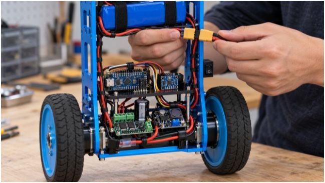
Clean power prevents the microcontroller from resetting during rapid motor reversals. DC motors generate massive inductive voltage spikes when switching directions.
Connect an 11.1V (3S) LiPo battery through an on/off switch directly to a high-efficiency buck converter. Step the voltage down to 5V to power the microcontroller and MPU6050. Run raw battery voltage directly to the motor driver power rail (TB6612FNG or L298N).
Place a $470\,\mu\text{F}$ electrolytic capacitor across the motor driver input terminals. This absorbs reverse EMF spikes that cause voltage drops on the microcontroller’s logic bus. Wire the MPU6050 SDA and SCL lines using short, twisted leads to avoid electromagnetic interference from the motor leads. For best design practices on noise suppression, review Texas Instruments Technical Documents.
Writing Deterministic PID and Filter Code
Control algorithms fail if cycle times fluctuate. Avoid using the standard delay() function inside your main loop.
Taming Sensor Noise with a Complementary Filter
A complementary filter extracts reliable angle data with minimal processing overhead:
C++
// Execute at fixed intervals (dt = 0.005s / 200Hz)
pitchAngle = 0.98 * (pitchAngle + gyroRate * dt) + 0.02 * accelAngle;
The high-pass coefficient (0.98) trusts the gyroscope for rapid adjustments, while the low-pass component (0.02) relies on the accelerometer to prevent long-term drift.
Overcoming Gearbox Deadband in Code
DC gearmotors do not move until the PWM signal overcomes internal brush and gear friction. If your algorithm outputs small correction values near vertical, the wheels will freeze, allowing the robot to fall. Measure this minimum threshold experimentally—usually around a PWM value of 35 on an 8-bit scale—and add it directly to your controller output:
C++
int deadband = 35;
if (pidOutput > 0) {
motorPwm = pidOutput + deadband;
} else if (pidOutput < 0) {
motorPwm = pidOutput – deadband;
} else {
motorPwm = 0;
}
This compensation linearizes your motor response around zero velocity, eliminating the dreaded balance shudder. Peer-reviewed inverted pendulum dynamics published on IEEE Xplore consistently demonstrate that nonlinear friction compensation stabilizes two-wheeled platforms under low tilt deviations.
The Systematic PID Tuning Sequence
The PID algorithm calculates corrective wheel velocity using three parameters:
Output(t)=Kpe(t)+Kie(t)dt+Kdde(t)dt
Where error e(t) is the difference between current pitch angle and physical balance point zero.
- Find Mechanical Equilibrium: Prop the robot upright with motors disabled. Read the serial output of your complementary filter. Find the angle where the robot naturally tips neither forward nor backward. Set this value as your balance setpoint.
- Increase Kp (Proportional): Set Ki and Kd to zero. Increase Kp in small steps until the robot attempts to balance, overshoots, and enters a steady, sustained oscillation.
- Increase Kd (Derivative): Add derivative gain to counter the overshoot. Kd acts like a virtual shock absorber by reacting to the rate of tilt change. Increase Kd until the wild oscillations settle into crisp, snappy corrections.
- Tune Ki (Integral): If your bot balances well but slowly drifts forward or backward across the room, inject a tiny amount of Ki. The integral term accumulates sustained errors over time and generates the push needed to bring the chassis to a standstill.
Frequently Asked Questions
1. Why does my self-balancing robot shake violently when standing?
Your Kp gain is set too high or your control loop execution frequency is drifting.
2. Can an Arduino Uno process PID math fast enough to balance a bot?
An Arduino Uno running an optimized 200 Hz loop executes integer and float operations within 2.5 milliseconds.
3. Should I mount the battery at the top or bottom of the frame?
Mount the battery near the top to raise the center of mass, slowing down rotational tipping speed.
4. How do I stop my robot from constantly drifting in one direction?
Calibrate your mechanical zero-point angle offset and apply a small integral gain (Ki) in software.
Stop Wobbling and Build It
A working self-balancing robot comes down to managing physical inertia, reliable loop timing, and eliminating motor deadband. Start by mounting your battery pack high on your frame, calibrate your MPU6050 gyro offsets while the platform rests on a level surface, and lock your PID loop to a strict 5-millisecond interval.
Once your upright platform stands rock-solid under human disturbance, wire in external range sensors or remote transceivers to transform your inverted pendulum into an agile autonomous vehicle.