A robot that sees a wall but still hits it needs more than a different distance threshold. I would check its power supply, motor speed, and sensor timing first. Building an obstacle avoiding robot using ultrasonic sensor and arduino becomes much easier when those three systems agree.
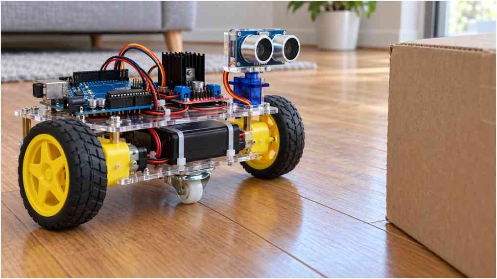
This design uses an Uno, an HC-SR04, an L298N, and a servo-mounted sensor. It slows the motors through PWM, scans both sides when blocked, and stops when distance readings become uncertain.
How the HC-SR04 Robot Makes Decisions
The sensor sends an ultrasonic burst and measures the returning echo. Distance equals the echo time multiplied by sound speed, divided by two. The division accounts for the outward and return journey.
The HC-SR04 datasheet hosted by SparkFun specifies a 10-microsecond trigger and recommends measurement cycles longer than 60 milliseconds.
This is reactive obstacle avoidance, not room mapping. The robot checks ahead, stops near an obstacle, compares side readings, and pivots toward greater clearance. A single sensor cannot see every hazard around the chassis.
Choose Components That Work Together
Use an Arduino Uno R3 or classic ATmega328P Nano, an HC-SR04, an L298N module, two geared DC motors, wheels, and a caster. Add a 2WD chassis, jumper wires, switch, and an optional SG90 servo with a sensor bracket.
Four motors are possible, but paired motors increase each driver’s current demand. Check combined stall current against the module’s practical thermal capacity. For a first build, I would keep two motors.
Choose the battery around motor ratings and driver losses. A protected two-cell lithium-ion pack supplies about 7.4V nominal and 8.4V fully charged. It requires a suitable charger and protection. A small rectangular 9V battery usually struggles with motor startup current.
Mount the sensor above the floor, facing forward. Keep the battery low and secure. For assembly planning, connect this section to your Obstacle avoiding robot build article.
Arduino Uno and L298N Wiring With PWM Speed Control
Sensor, Servo, and Motor Connections
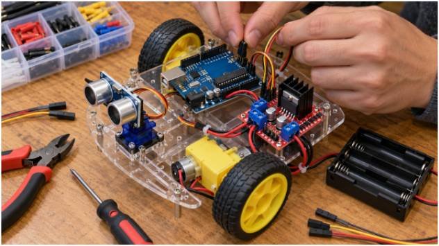
Connect HC-SR04 VCC to 5V, GND to ground, TRIG to A1, and ECHO to A2. Connect the servo signal to pin 10.
Wire L298N IN1, IN2, IN3, and IN4 to pins 4, 5, 6, and 7. Connect the left motor to OUT1/OUT2 and the right motor to OUT3/OUT4.
Remove the ENA and ENB jumper caps. Connect ENA to pin 3 and ENB to pin 11. These pins support PWM while the servo library operates.
This corrects the earlier ENB-to-pin-9 arrangement. Arduino’s official Servo library documentation explains that the library disables PWM on pins 9 and 10 on these boards.
The STMicroelectronics L298 documentation describes separate enable inputs for the bridges. PWM on those inputs changes motor drive duty cycle; it does not guarantee a specific wheel speed.
Power Without Random Resets
Connect battery positive through a switch to the driver’s motor-supply terminal. Join battery negative, driver ground, Arduino ground, and servo-supply ground.
Use a regulated 5V supply with enough current for the servo’s startup and stall demand. For initial testing, power the Uno by USB and keep motor power separate, with shared grounds.
Do not connect the driver’s 5V output to Arduino Vin. Module regulator jumpers vary, so check your module’s instructions before joining any 5V rails. Keep motor current out of breadboard power tracks.
Upload the Arduino Obstacle Avoidance Code
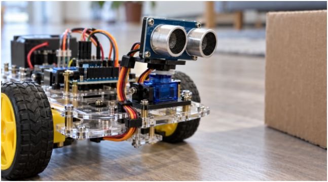
Select your board and port in Arduino IDE. Use the complete sketch in the appendix below. Lift the wheels before the first powered test.
The code starts with the motors disabled. It uses a 25cm obstacle threshold, a cruising PWM value of 160, and slower turning at 140. These are starting points, not universal motor specifications.
It also sets an explicit echo timeout. Arduino’s pulseIn reference confirms that a missing complete pulse returns zero. The sketch converts that result to “unknown,” stops, and retries.
Unlike the original sketch, it does not automatically reverse. There is no rear sensor to confirm clearance. Both valid side readings must exceed the threshold before it chooses the clearer direction; otherwise, it waits.
Calibrate Distance, Speed, and Turning
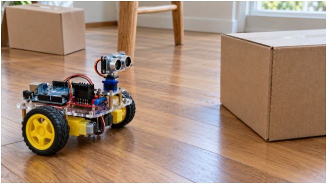
Start on a level floor with a large cardboard obstacle. Measure from the sensor face, then compare readings at 15, 25, and 50cm. Soft fabric, narrow chair legs, and angled surfaces can return unreliable echoes.
Here is a worked design example, not a measured result. Assume the robot travels at 0.30m/s and needs 0.12 seconds to detect and react. It travels 3.6cm during that delay. Add an assumed 5cm coast distance, a 4cm bumper offset, and a 5cm margin: the required threshold becomes 17.6cm.
A 25cm starting threshold covers those assumptions. Faster travel or slippery flooring can demand more room. Measure actual coast distance because disabling ENA and ENB allows coasting rather than active braking.
Adjust turning duration in small steps. Timed turns vary with battery charge, floor grip, and wheel alignment. Confirm that servo angles 20 and 160 actually face right and left without binding.
Troubleshoot Before Replacing Parts
If the robot spins, disable power and swap the leads on the reversed motor. Test each wheel direction with the chassis raised.
If it clicks without moving, check battery voltage under load, terminal connections, and the minimum PWM needed to start. Values such as 120–140 are not guaranteed starting thresholds.
If readings jump or the Uno resets, inspect shared grounds and servo power. Route sensor wires away from motor leads. If the driver overheats, reassess current demand and cooling.
Once avoidance works, your Wall-following maze robot article makes a useful next project. Explain that wall following needs different sensing and control logic.
Your Robot Can Dodge. Now Make It Dependable.
I would rather see ten calm obstacle tests than one lucky escape. Start slowly, record your settings, and change one variable at a time. Your next step is simple: test a flat wall, an angled box, and a chair leg before increasing speed.
Frequently Asked Questions
1. Can I build this robot without a servo?
Yes; use a fixed front sensor and brief chassis turns to check another direction while stopped.
2. Why does PWM fail when I attach the servo?
On the Uno and classic Nano, Servo uses Timer1; move motor PWM from pins 9/10 to pins 3/11.
3. Which battery should I use?
Choose a protected pack that meets motor voltage and current requirements, plus a regulated supply for the electronics.
4. Can this robot detect stairs?
No; a forward-facing ultrasonic sensor needs additional downward-facing sensing to detect floor edges reliably.