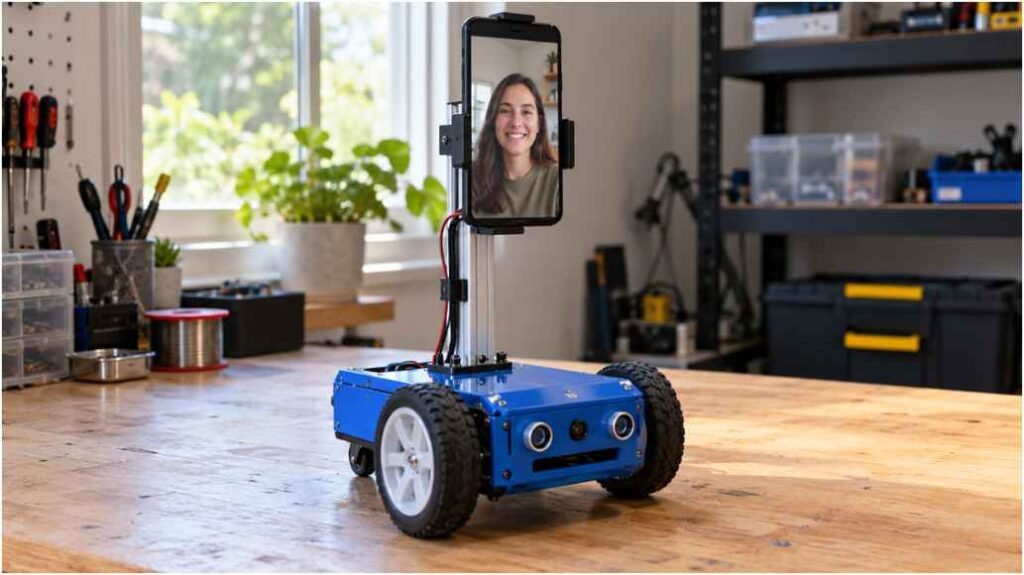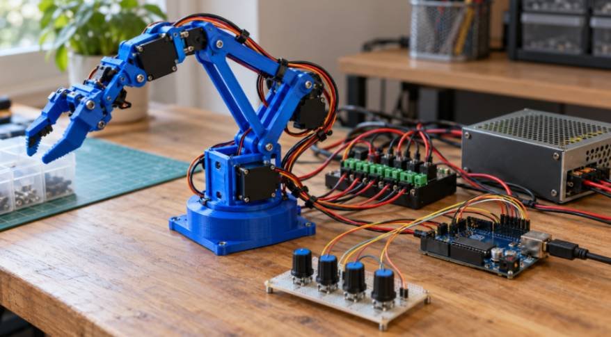
I would check battery placement before blaming weak motors for a robot that spins its wheels. A powerful drivetrain can struggle when too much weight rests on a caster or one drive wheel barely touches the floor. Understanding how weight distribution affects robot traction helps explain why rearranging existing components can sometimes improve movement more than upgrading hardware.
The goal is to give driven wheels enough load to transmit useful force while preserving stability. That balance changes with drivetrain layout, payload position, acceleration, and terrain.
Why Weight Placement Changes Wheel Grip
Traction is the force a wheel transmits through its contact with the ground. On a firm surface, a useful starting estimate is:
Maximum traction force ≈ friction coefficient × normal force.
Normal force is the supporting force acting perpendicular to the surface. On level ground, stationary wheel loads together support the robot’s weight. However, individual wheels rarely carry equal shares automatically.
A battery near a passive caster increases that caster’s load. Because the caster supplies no driving torque, this arrangement can leave less normal force available at the powered wheels.
Traction Limits Versus Motor Limits
Wheelspin usually indicates that commanded wheel torque exceeds available grip. Stronger motors alone cannot fix that condition.
A robot that stops moving without wheelspin may instead lack usable torque, encounter excessive resistance, or reach an electrical limit. Diagnose the behavior before changing weight placement.
A Simple Example of Better Weight Distribution

Consider a hypothetical 10-kilogram robot weighing approximately 98.1 newtons. If its powered wheels support 60% of that weight, their combined normal load is about 58.9 newtons.
With an assumed friction coefficient of 0.6, the simplified traction limit is approximately 35.3 newtons.
Moving existing components so those wheels support 80% raises the estimate to 47.1 newtons. Total mass remains unchanged, but more weight now supports propulsion.
Weight distribution is only one factor influencing traction; wheel diameter also affects how effectively a robot converts motor torque into ground force.
Larger wheels can improve obstacle traversal and increase travel distance per revolution, but they also require greater torque to deliver the same driving force at the contact surface. Understanding how wheel diameter affects robot movement helps you evaluate these trade-offs alongside wheel loading, traction, and drivetrain performance when optimising a mobile robot.
This example illustrates how weight distribution affects robot traction without suggesting that every robot needs an 80% drive-wheel load. Actual targets depend on support geometry, tipping resistance, wheel construction, and operating conditions.
Does Every Wheel Need Equal Weight?
Equal loading is a useful starting point for some platforms, but it is not a universal design rule.
Two Driven Wheels With Casters
A differential-drive robot needs sufficient load on both powered wheels. Excessive caster loading can encourage wheelspin, while extreme drive-axle loading can reduce stability in certain configurations.
Keep the battery low and adjust its position gradually. Maintain reliable support at every intended contact point.
Four-Wheel Drive and Mecanum Platforms
Four powered wheels can contribute propulsion, provided they maintain contact and receive suitable torque. However, a rigid chassis on uneven ground may unload one wheel even when the components look balanced.
Mecanum platforms also benefit from consistent wheel contact and reasonably balanced loading. Their angled rollers make motion sensitive to wheel forces, so one lightly loaded corner can complicate strafing.
Skid-steer platforms introduce another tradeoff: increased grip can increase resistance during tight turns because wheels must scrub sideways.
What Changes During Driving?
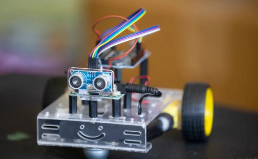
Stationary balance does not describe every operating condition.
Forward acceleration transfers normal load toward the rear; braking transfers it toward the front. A higher center of mass generally increases this transfer for the same acceleration and wheelbase.
Consequently, front drive wheels may lose available grip during acceleration. Rear drive wheels can gain load, although aggressive acceleration may still cause pitching or tipping.
Slopes change both wheel loading and the force needed to move. A lifting arm creates additional changes by moving the combined center of mass upward or outward.
Uneven wheel loading can also influence how consistently a mobile robot follows its intended path, particularly when differences in traction cause the wheels to slip at different rates. Understanding the relationship between wheel speeds, track width, and drivetrain geometry can help diagnose unexpected turning behaviour and improve manoeuvrability.
Learn how to calculate a robot’s turning radius to estimate turning paths, assess obstacle clearance, and verify steering performance under realistic operating conditions.
Test the robot with its payload lowered, raised, and extended. A configuration that works while empty may behave differently during its actual task.
How to Measure and Improve Wheel Loading
Measure With Level Supports
Place a suitable scale beneath each wheel simultaneously, or measure sequentially using equal-height supports beneath the other wheels. Keep the chassis level and use the normal operating configuration.
Record individual readings and check that their sum approximately matches total weight. Compare left and right drive-wheel loads, then repeat with different payload positions.
Scale readings in kilograms indicate supported mass equivalents; multiply by gravitational acceleration when calculating forces in newtons.
Move Components Before Adding Ballast
Try repositioning the battery, electronics enclosure, or payload mount first. Keep heavy components low and securely fastened.
Ballast can improve drive-wheel loading, but it also adds mass that must accelerate and climb. Check motor current, operating temperature, structural capacity, and stopping behavior after substantial changes.
Repeat a controlled driving test on the same surface with the same payload and speed settings. Record wheelspin, travel consistency, and turning behavior.
Why Terrain Still Matters

The simple friction model works best as an initial estimate on firm surfaces. Tire material, contamination, deformation, and operating conditions affect actual grip.
Loose soil introduces sinkage and soil shearing. Concentrating weight on one wheel may make it dig deeper, increasing resistance instead of improving progress.
Beyond traction, a mobile robot’s ability to traverse uneven terrain depends on the clearance beneath its chassis and the position of its lowest components.
Even when the driven wheels have sufficient grip, a low-mounted bracket or battery enclosure can catch on ridges, thresholds, and surface irregularities. Understanding ground clearance in mobile robots helps you assess underbody contact risks and balance obstacle traversal with wheel geometry, payload, and stability.
Suspension or compliant wheel mounts can help maintain contact over irregular ground. Evaluate performance on the intended surface rather than assuming results from a smooth workshop floor will transfer everywhere.
Frequently Asked Questions
1. How can I test how weight distribution affects robot traction?
Measure wheel loads, reposition one component, and repeat the same driving test. Keep tires, surface, payload, and acceleration settings consistent.
2. Does adding weight always improve grip?
No. It may increase driven-wheel normal force, but it also increases movement demands and can worsen sinkage or exceed component limits.
3. Can uneven loading make a robot turn unpredictably?
Yes. Different available grip between wheels can produce unequal slipping, particularly during acceleration or demanding turns.
Final Thoughts
I would check wheel loading before spending money on stronger motors or different tires. Moving a battery, lowering a payload, or correcting an uneven mounting point may improve grip without adding weight. The most useful adjustment is one that helps the robot accelerate, turn, and stop consistently while remaining stable.
I would also test each change under realistic conditions. A robot that moves smoothly on a level floor may struggle on a ramp or behave differently with its arm extended. Measuring wheel loads and repeating the same driving tests makes those differences easier to understand. Change one thing at a time, record the results, and use that evidence to find a balance that works throughout the robot’s operating cycle.