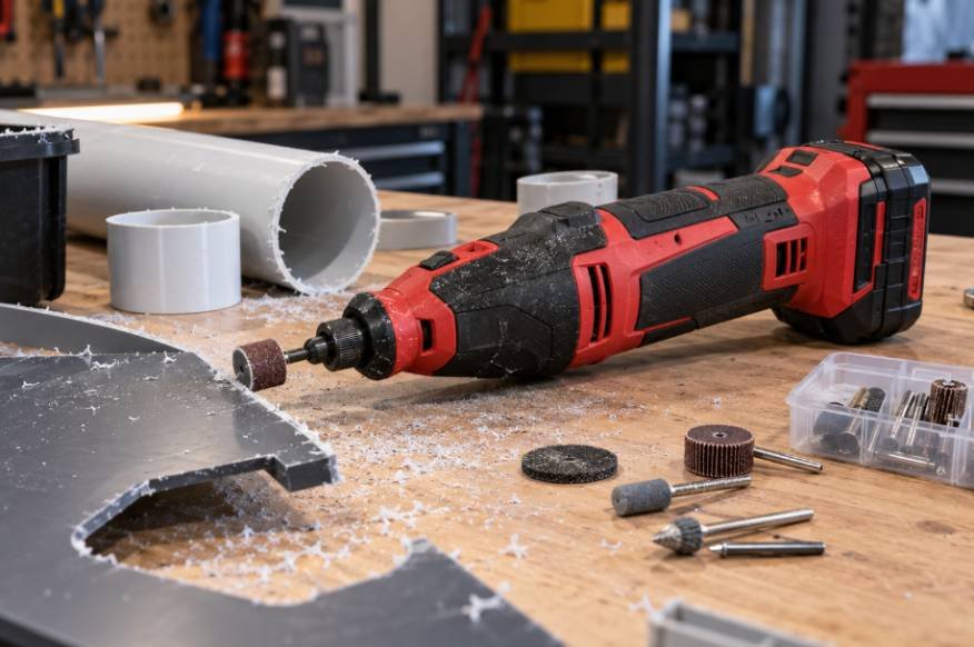
I start planning robot turns by asking which point on the chassis I want to track. A robot’s axle midpoint, outside wheel, and front corner follow different circles.
Understanding how to calculate a robot’s turning radius starts with choosing that reference point and identifying the drivetrain. From there, a few measurements can predict whether a classroom rover will follow a smooth curve or clear a workshop obstacle.
What Turning Radius Actually Measures
Turning radius is the distance between a chosen reference point and the instantaneous center of rotation—the point around which the robot turns at that moment.
For differential drive, the reference is usually the midpoint between the driven wheels. For a car-like bicycle model, it is the rear-axle midpoint. Turning diameter is twice the corresponding radius.
Neither measurement automatically describes the clearance required by the entire chassis.
Turning radius is particularly important when designing robots that must manoeuvre around confined workspaces or position tools with precision. For projects involving robotic arms, the relationship between the mobile platform’s movement and the arm’s working envelope can influence reach, positioning accuracy, and obstacle clearance.
This Hands on DIY robotic arm project provides additional context for understanding robotic mechanisms, component integration, and the design considerations involved in building functional robotic systems.
Measure Your Robot Before Calculating
Measure track width, represented here by b, between the centerlines of the left and right driven wheels. Avoid measuring between the outside tire edges.
For car-like steering, measure wheelbase L between the front and rear axles. Track width and wheelbase describe different dimensions.
Use consistent units throughout. Inches work with inches per second; millimeters work with millimeters per second. Record actual wheel speeds whenever possible because identical motor commands do not guarantee identical movement.
Calculate Differential-Drive Turning Radius

A differential-drive robot changes direction by running its left and right wheels at different speeds. Under ideal rolling conditions:
R = (b ÷ 2) × (vR + vL) ÷ (vR − vL)
Here, vR and vL are signed right-wheel and left-wheel ground speeds. Forward speeds are positive; reverse speeds are negative. Report the absolute value when you only need the radius magnitude.
Worked Example
Suppose a rover has a 12-inch track width. Its right wheel travels at 18 inches per second, while its left wheel travels at 12 inches per second.
R = (12 ÷ 2) × (18 + 12) ÷ (18 − 12)
R = 6 × 30 ÷ 6 = 30 inches
The axle midpoint follows a circle with a 30-inch radius. The wheel centerlines follow radii of 24 and 36 inches.
Understand the Special Cases
Equal wheel speeds in the same direction produce straight travel, corresponding to an infinite radius. If both wheels stop, the robot is stationary and has no defined turning path.
Equal and opposite speeds produce a center spin with zero center-path radius. Stopping one wheel produces a pivot around that wheel, giving the axle midpoint a radius of b ÷ 2.
Calculate Turning Radius for Car-Like Steering
For a robot using conventional front-wheel steering, the simplified bicycle model gives:
R = L ÷ tan(δ)
The symbol δ represents the equivalent bicycle-model steering angle, rather than automatically matching either individual front-wheel angle.
For an 18-inch wheelbase and a 30-degree equivalent steering angle:
R = 18 ÷ tan(30°) ≈ 31.2 inches
This is the rear-axle midpoint’s radius. Actual Ackermann steering uses different inner and outer wheel angles. Maximum steering travel determines the smallest achievable radius under this model.
Convert Wheel RPM Into Ground Speed

When learning how to calculate a robot’s turning radius, converting motor information correctly prevents misleading results.
For wheel diameter D and wheel speed n in revolutions per minute:
v = π × D × n ÷ 60
A four-inch wheel rotating at 60 RPM has an ideal ground speed of approximately 12.57 inches per second.
Wheel diameter directly influences the relationship between rotational speed and a robot’s linear velocity, making it an important factor when calculating turning performance. Larger wheels cover more ground per revolution, but they can also increase torque requirements and affect acceleration, traction, and obstacle traversal.
For a deeper understanding of these trade-offs, examine how wheel diameter affects robot movement and how wheel size influences a mobile robot’s overall performance.
If your specification gives motor-shaft RPM, apply the gearbox reduction first. Encoder measurements should also account for gearing and the encoder’s counting convention.
Choose Wheel Speeds for a Target Curve
You can reverse the differential-drive calculation when you already know the desired radius.
First calculate angular velocity:
ω = v ÷ R
Then calculate each wheel speed:
vR = v + ωb ÷ 2
vL = v − ωb ÷ 2
Use radians per second for ω. If either wheel exceeds its speed limit, reduce both wheel speeds proportionally to preserve the planned radius.
Check Clearance and Verify the Result
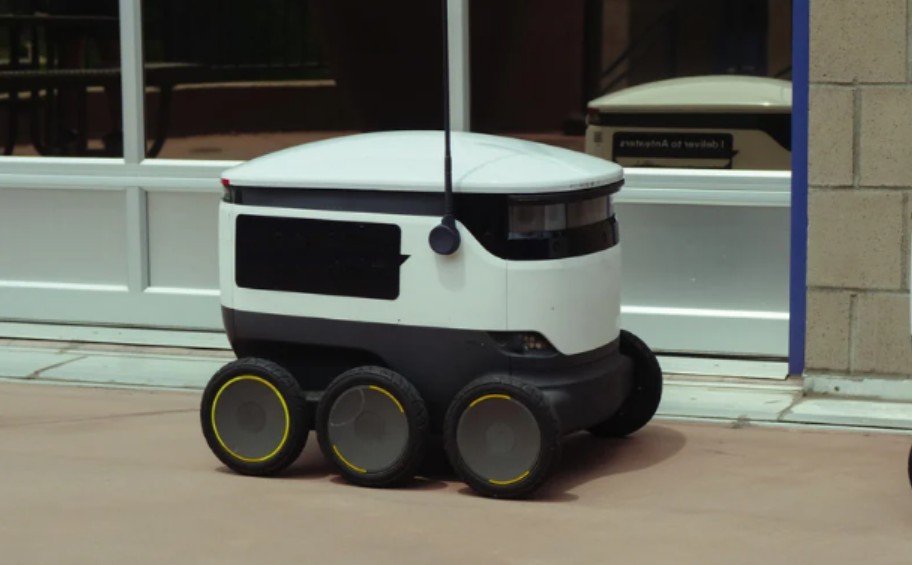
A zero-radius spin still sweeps the chassis through space. Check the farthest corner, bumper, sensor, and attachment relative to the rotation center. Allow additional clearance for tracking error.
Turning accuracy is only one aspect of reliable mobile robot navigation; the chassis must also maintain sufficient clearance when crossing uneven surfaces or approaching obstacles.
Before finalising a turning path, assess the space beneath the robot’s lowest components and consider how wheel geometry, payload, and terrain affect its ability to manoeuvre without scraping or becoming stuck. A Detailed Explanataion of ground clearance in mobile robots explains how to evaluate underbody clearance and balance obstacle traversal with stability and dependable movement.
To verify your calculation, drive slowly through a complete circle on a flat surface. Track the axle midpoint using overhead video or a suitable marker, measure the resulting diameter, and divide by two.
Repeat clockwise and counterclockwise with the normal payload. Tire slip, caster resistance, unequal wheel diameters, and motor mismatch can change the measured path. Tracked and skid-steer platforms especially need practical calibration because turning involves lateral scrubbing.
Frequently Asked Questions
1. What measurements show how to calculate a robot’s turning radius?
Differential drive requires track width and both wheel ground speeds. Car-like steering requires wheelbase and the appropriate steering angle.
2. Does driving faster always increase turning radius?
No. In the ideal differential-drive model, increasing both wheel speeds proportionally preserves radius. Real traction limits can change the result.
3. Can two recorded positions reveal the radius?
Positions alone are insufficient. For a constant circular arc, chord distance d and heading change Δθ give R = d ÷ [2 sin(Δθ ÷ 2)] in magnitude.
Make Every Turn More Predictable
I treat every turning-radius calculation as a starting point, then check how closely the robot follows that curve on its actual driving surface. Accurate wheel measurements and the correct drivetrain formula provide a useful prediction, but repeatable movement also depends on traction, motor control, payload, and chassis clearance.
Before adjusting the code, I would compare several slow clockwise and counterclockwise turns under the same conditions. Consistent differences can help reveal unequal wheel speeds or a measurement error, while unpredictable results may point to slipping tires or changing surface conditions. Recording those tests makes each adjustment easier to evaluate.
My goal is a robot that follows its intended path while keeping every corner and attachment clear of nearby obstacles. Combining the calculation with careful testing makes turns more reliable, whether the robot navigates a classroom course, a garage workspace, or a narrow storage aisle.