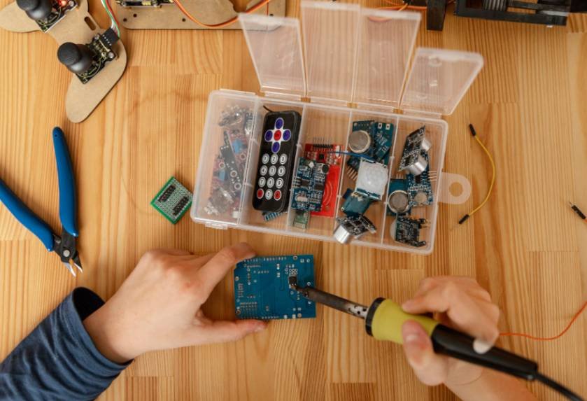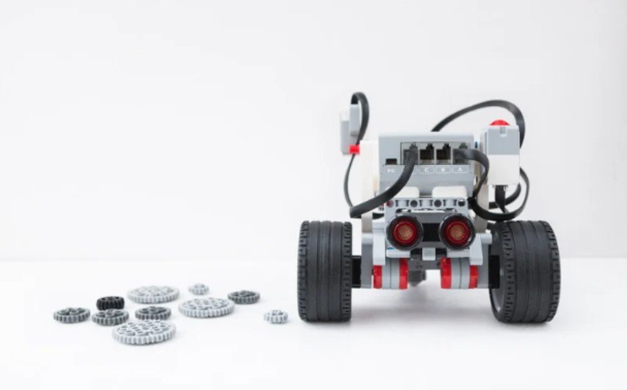
I judge a mobile robot’s design by what happens when smooth flooring ends. A machine can navigate beautifully across a workshop yet stop at a doorway because one bracket hangs too low. When approaching ground clearance in mobile robots explained, with that practical problem identifying what might touch the ground before the wheels carry the robot across it.
The right clearance protects components and supports reliable movement. Choosing it requires understanding terrain, payload, wheel geometry, and stability together.
What Is Ground Clearance?
Ground clearance is the vertical distance between a level supporting surface and the lowest non-ground-contacting part of a robot. That part might be the chassis plate, gearbox housing, battery enclosure, or exposed fastener.
Overall robot height does not reveal this measurement. A tall robot can have little space beneath its frame, while a compact platform can provide substantial underbody clearance.
Clearance also differs from maximum obstacle height. Wheels may climb an obstacle taller than the static underbody gap as the chassis rises, provided traction, torque, and geometry allow it.
How to Measure Clearance Correctly
Find the Actual Lowest Point
Place the robot on a hard, level surface with power disabled. Inspect underneath from several directions, checking motor mounts, screw heads, protective covers, and cable loops.
Measure vertically from the supporting surface to each potential contact point. Record the smallest gap rather than measuring only beneath the center plate. A ruler or measured spacer can help reach awkward locations.
Measure With the Intended Payload
Install the battery, sensors, enclosure, and expected payload before taking your final measurement. Weight can compress tires, deflect the frame, and compress suspension.
For example, a robot measuring 30 mm unloaded might have only 24 mm beneath its lowest bracket when loaded. Those figures are illustrative, but the measurement difference matters.
Also check clearance as suspension moves through its operating range. A stationary measurement cannot describe every position encountered during travel.
Why Robots Scrape or Become High-Centered
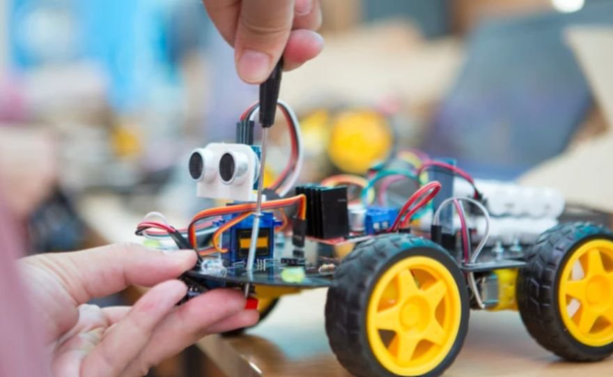
Scraping happens when an underbody component contacts the surface. High-centering occurs when terrain supports the underside enough to reduce wheel loading, potentially leaving insufficient traction to move.
A narrow ridge between the axles can cause trouble even when the front wheels climb it successfully. Long wheelbases and low central components increase vulnerability to certain crests.
Other failures look similar but require different fixes. A wheel spinning against a threshold may indicate inadequate traction or torque. A small caster catching an edge may prevent progress before the chassis approaches contact.
How Wheels and Chassis Geometry Change Performance
Wheel Diameter and Casters
Larger wheels generally negotiate abrupt edges more easily, but their benefits come with drivetrain consequences. For the same required driving force, increasing wheel radius increases wheel torque demand.
Wheel diameter influences more than a robot’s ability to clear obstacles; it also affects torque requirements, driving force, and overall movement efficiency.
Understanding how wheel diameter affects robot movement can help you evaluate the trade-offs between increasing ground clearance, maintaining adequate traction, and preserving reliable performance across uneven terrain.
If axle locations remain unchanged relative to the chassis, larger wheels raise the frame. However, clearance improvements depend on the complete mounting arrangement.
Check caster diameter and mounting height too. Large drive wheels cannot compensate for a trailing caster that repeatedly jams at doorway thresholds.
Approach, Departure, and Breakover Angles
Approach angle describes the front-end geometry that determines whether an obstacle or ramp contacts the overhang before the wheels engage it. Departure angle describes the corresponding rear-end limitation.
Breakover angle concerns crossing a crest without the underside contacting it between the axles.
Shortening overhangs, relocating low components, or changing wheelbase can improve these geometric limits. Raising the entire chassis is only one possible solution.
Choosing Clearance Without Sacrificing Stability
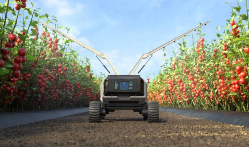
There is no universal ideal clearance. Smooth indoor routes, gravel paths, lawns, and agricultural rows present different requirements.
Start by measuring representative obstacles, including their width, shape, spacing, and approach direction. Include floor transitions, cables, drainage channels, and surface irregularities.
Raising heavy components can increase center-of-gravity height and reduce tipping resistance. Keep batteries and other dense equipment low where practical while protecting their underside.
Suspension can help maintain wheel contact, but clearance alone does not provide shock absorption. Likewise, extra clearance cannot prevent tires from sinking into soft soil. Tire contact area, loading, and soil properties require separate consideration.
Test the Complete Robot on Representative Terrain
Begin with low-speed trials using secured obstacles that represent the intended route. Test with the expected payload and repeat approaches from different directions.
Reliable terrain testing also depends on understanding how a robot interprets its surroundings and converts sensor readings into appropriate responses.
From detecting obstacles to estimating position and adjusting movement, sensors provide the information that enables a robot to navigate changing environments more effectively. Explore how robot sensors work, from signal detection to intelligent actions to understand how sensing systems support obstacle awareness, navigation, and safer operation across uneven terrain.
Watch for front strikes, central contact, rear scraping, wheel slip, and caster obstruction. Stop when contact or instability appears rather than repeatedly forcing the robot forward.
Diagnosing these issues becomes easier when you distinguish between the components that detect environmental conditions and those that produce physical movement.
Sensors provide information about obstacles, terrain, and robot position, while actuators drive the wheels or adjust mechanical components in response to control commands.
This complete comparison of sensors and actuators in robotics explains how these complementary systems contribute to navigation, obstacle handling, and dependable mobile robot performance.
Change one design variable at a time and record the result. After successful slow trials, evaluate intended operating speeds under controlled conditions.
Frequently Asked Questions
1. What Does Ground Clearance in Mobile Robots Explained Mean for Beginners?
It means understanding the usable space beneath a robot and how that space affects movement. The practical goal is avoiding underbody contact while maintaining traction and stability.
2. Is Higher Ground Clearance Always Better?
No. Additional clearance may help with obstacles, but raising the robot’s mass can reduce stability. Choose clearance around the actual route and loaded configuration.
3. Can Larger Wheels Fix Every Clearance Problem?
No. Overhangs, low brackets, inadequate torque, poor traction, and small casters can still prevent traversal. Diagnose the contact or motion failure before changing wheels.
Final Thoughts
I see ground clearance as a practical design choice that needs testing under real conditions. Measure beneath the robot’s lowest component with its intended payload installed, then check how it handles thresholds, crests, and uneven surfaces. Balance clearance with traction, wheel geometry, and stability to build a robot that moves reliably along its intended route.