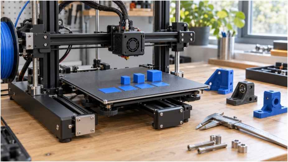
A bracket can look flawless and still refuse its bolt. I approach how to calibrate a 3d printer for functional mechanical parts by measuring the features that must mate: holes, shafts, slots, and mounting centers.
For an FDM printer, the useful sequence is mechanical checks, first-layer setup, extrusion calibration, dimensional testing, and assembly validation. Changing settings in that order helps prevent one correction from hiding another problem.
Define the Fit Before Changing Settings
I start with the drawing, not a calibration cube. Identify which dimensions control assembly and which only affect appearance.
A loose cable opening needs less precision than a bearing pocket. Specify whether a joint should slide, rotate, snap together, or hold an interference fit. “Accurate” means little without an acceptance limit.
Keep CAD and slicer measurements in millimeters, even when buying inch-sized hardware in the United States. A nominal quarter-inch shaft measures 6.35 mm; it is not interchangeable with a 6 mm shaft.
Use clean calipers, check zero, and measure each feature several times with light pressure. Caliper resolution does not equal measurement accuracy. Small internal holes are particularly difficult; use the actual mating hardware or suitable gauges to verify fit.
Fix Mechanical Play and First-Layer Errors
With the printer cool and powered down, inspect belt condition, pulley screws, carriage movement, and gantry alignment. Follow the manufacturer’s tension procedure. Overtightening belts can create new problems.
Check that the hotend and bed mounts are secure. Clear nozzle debris, clean the build surface, and run the manufacturer’s bed and probe calibration.
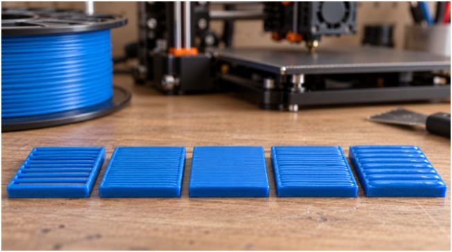
Print a first-layer patch. Lines should join without open gaps, heavy ridges, or scraping. A bed mesh compensates for surface variation; it cannot repair loose hardware.
Next, print a short block and compare its base width with its middle. A wider base suggests elephant foot. Correct excessive first-layer compression or inappropriate bed temperature before adding compensation.
Keep the same plate, nozzle, and material throughout testing. Otherwise, comparisons become less useful.
Calibrate Extrusion and Filament Flow
Verify Extruder Movement
Extruder calibration checks filament movement. Flow calibration checks how that material prints. Treat them as separate adjustments.
On supported, user-configurable machines, follow the firmware’s extrusion measurement procedure. Do not overwrite factory settings on a closed printer without manufacturer guidance.
For Klipper, the official rotation-distance documentation specifies:
New rotation distance = old rotation distance × actual movement ÷ commanded movement.
If 50 mm is commanded but 48 mm moves, a 22 mm setting becomes 21.12 mm. Repeat the measurement before saving. E-steps use the inverse ratio, so these formulas are not interchangeable.
Do not change X, Y, or Z motion settings merely because a printed cube measures undersize. Material shrinkage and extrusion effects can distort that test.
Tune Temperature, Flow, and Pressure Advance
Dry filament according to its manufacturer’s instructions when moisture is suspected. Start within the recommended temperature range and test using your intended material.
Choose temperature for consistent extrusion and layer bonding, rather than appearance alone. Then tune flow using a dedicated test.
Prusa’s extrusion-multiplier procedure offers visual and measured methods. It also warns that inexpensive calipers may not reliably measure a single printed wall. Use small adjustments and reprint.
Save flow settings per material profile. Ellis’ tuning guide explains that the appropriate multiplier can vary across filament brands, types, and even spools.
Finally, tune pressure advance or linear advance if supported. This manages extrusion during speed changes. It can improve corners, but cannot correct warped parts or incorrect CAD clearances.
Measure Dimensional Accuracy at Multiple Sizes
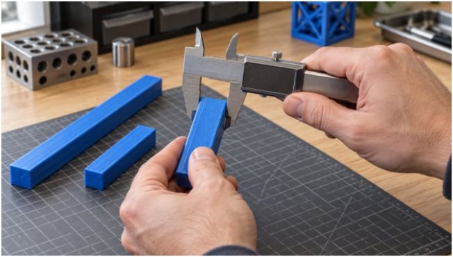
A single cube cannot distinguish a fixed outline error from proportional shrinkage. I would compare several sizes before deciding which setting to change.
Print 20 mm and 80 mm test bars along both X and Y. Keep wall settings, orientation, and layer height consistent. Let them cool fully before measuring.
Consider this illustrative example, not a printer test result: a 20 mm bar measures 19.80 mm, while an 80 mm bar measures 79.80 mm.
Both are short by 0.20 mm. That pattern suggests a constant offset worth investigating. Scaling everything would overcorrect one size relative to the other.
Now suppose the bars measure 19.90 mm and 79.60 mm. Both are 0.5% short. A provisional scale calculation is:
Correction factor = nominal dimension ÷ measured dimension.
For the longer bar, 80 ÷ 79.60 = 1.00503, or about 100.50%.
This diagnoses a pattern; it does not prove the cause. Check warping, measurement consistency, and axis behavior before applying material shrinkage compensation. Validate another size afterward.
Check Z separately. Measure taller coupons away from first-layer distortion, and remember that layer height affects achievable vertical dimensions.
Tune Hole Compensation and Assembly Clearances
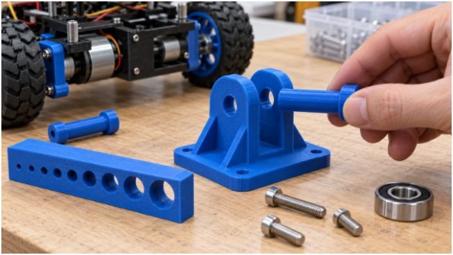
External dimensions and internal holes can need different corrections. Enlarging an entire model to fit a bolt may spoil mounting-center spacing.
OrcaSlicer’s official precision documentation separates hole compensation, contour compensation, and elephant-foot compensation. Use the control matching the error, then inspect the sliced preview.
For a practical coupon, include a pin, several holes, a slot, and two mounting holes. Copy the intended part’s orientation and wall settings.
For a nominal 10 mm printed pin, try CAD holes of 10.10, 10.20, 10.30, and 10.40 mm. These provide experimental diametral clearances, not guaranteed fits. A 0.20 mm diametral gap leaves 0.10 mm per side.
Select the smallest clearance that works after cooling. Test press fits gradually; brittle parts can crack. Precision bearing seats may need machining or reaming.
When choosing a 3d printer for beginner robotics projects, prioritize repeatable motion and stable profiles alongside build volume.
Before you 3d print a robot chassis with arduino, test mounting centers using the actual board and fasteners. Avoid sanding away a dimensional problem that affects every replacement part.
Validate Strength and Repeatability
Correct dimensions do not guarantee useful strength. Orient loaded features to reduce stress across layer interfaces, and keep seams away from critical mating surfaces where practical.
Print a representative bracket section using the final wall count, material, and orientation. Check bolt seating, cracks, flex, and fit under the expected load.
Repeat the coupon three times. Record the minimum, maximum, and average of each critical measurement. If the variation exceeds your allowed tolerance, compensation alone cannot deliver reliable assemblies.
Save the filament identity, temperatures, flow, compensation, orientation, and results with the profile. Recheck after nozzle changes, maintenance, or material changes.
Make the Parts Fit, Then Hit Print
I would rather spend filament on one useful coupon than another full-size bracket that needs persuasion with a drill. Define the fit, correct the underlying error, and verify the assembly before committing to production.
Your next step is simple: print a small section containing your hardest mating feature. Make that work reliably first.
Frequently Asked Questions
1. What should I test first when learning how to calibrate a 3d printer for functional mechanical parts?
Check mechanical play and first-layer quality before tuning extrusion, dimensions, or mating clearances.
2. What clearance should I use for moving printed parts?
Test a clearance ladder in the final material and orientation; no single gap works for every printer.
3. Should I change axis steps to fix undersized holes?
No; investigate flow, hole geometry, shrinkage, and hole compensation before changing motion calibration.
4. How often should I recalibrate functional prints?
Verify critical fits after nozzle changes, maintenance, new materials, or unexplained dimensional drift.