Transistors show up in almost every kind of electronic device, but their basic switching action is surprisingly easy to understand. A simple transistor switch circuit for beginners lets you see that principle in action by using a small input signal to control an LED or another low-power load.
In this blog, I’ll walk through a basic NPN low-side switch using a 2N2222 or BC547, explain how the base, collector, and emitter work together, and show why concepts such as cutoff, saturation, and current limiting matter.
What Does a Transistor Switch Actually Do?
An NPN transistor has three terminals: collector, base, and emitter. The base acts as the control connection. A small base current allows a larger collector current to flow through the load and down through the emitter to ground.
In a low-side transistor switch circuit, the load sits between the positive power supply and the transistor collector. The emitter connects to ground. When the transistor turns on, it completes the return path to ground and powers the load.
This arrangement is widely used because it is simple, reliable, and easy to control with switches, sensors, or microcontrollers. It also fits naturally into the best breadboard layout for beginner circuits, where the power rails, transistor, load, and control connections can be separated clearly for easier wiring and troubleshooting.
What Components Do You Need for a Beginner Transistor Switch?
For a basic 5V LED circuit, I would use an NPN transistor such as a BC547 or 2N2222, a standard 5 mm LED, a 330-ohm to 470-ohm LED resistor, a 1 kΩ to 4.7 kΩ base resistor, a breadboard, jumper wires, and a 5V DC source.
You can control the base with a push-button, jumper wire, Arduino output, or another digital signal.
A small battery pack or regulated 5V supply is a better choice for learning than experimenting with high voltages.
How Do You Wire a Simple NPN Transistor Switch Circuit?
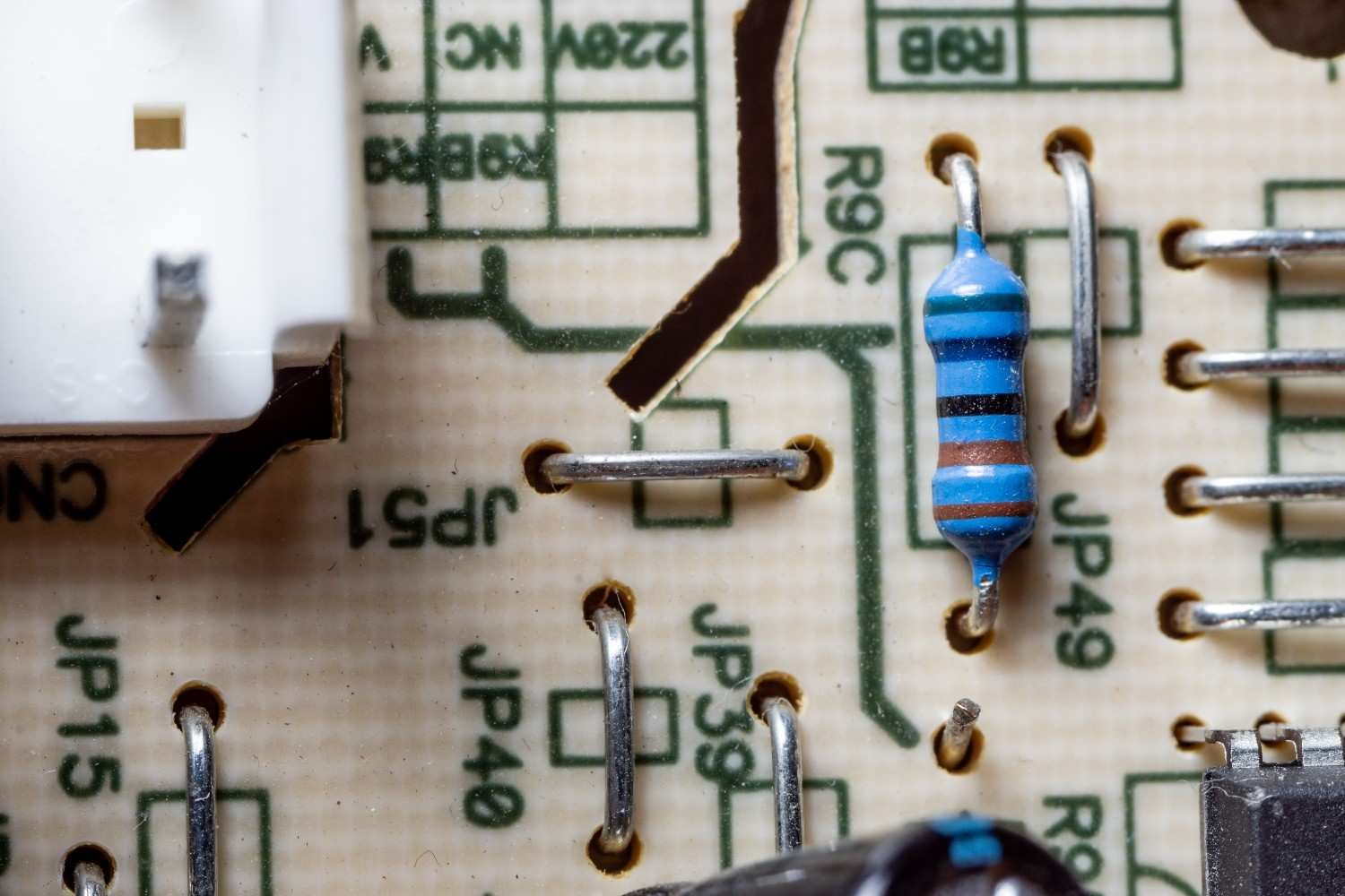
The basic current path should look like this:
+5V
|
330Ω–470Ω
|
LED
|
Collector
|\
Input–| > NPN Transistor
via |/
1kΩ–4.7kΩ
|
Emitter
|
GND
The positive supply connects to the LED through its current-limiting resistor. The LED’s other side connects to the collector of the transistor. The emitter connects directly to ground.
The control signal reaches the transistor base through the base resistor.
This is the core layout I would use when building a simple transistor switch circuit for beginners on a breadboard.
How Do You Build the Circuit Step by Step?
How Do You Identify the Transistor Pins?
Before connecting anything, check the datasheet for your exact transistor.
BC547, 2N2222, PN2222, P2N2222A, and similar devices may use different pin arrangements depending on the package and manufacturer. I would never rely only on the flat side of the transistor or a generic diagram found online.
Identify the collector, base, and emitter from the manufacturer’s documentation before applying power.
How Do You Connect the Emitter?
Connect the emitter directly to the ground rail of your breadboard.
If you are using an Arduino or another controller, its ground should connect to the same ground rail so both sides of the circuit share a common electrical reference.
How Do You Connect the LED Load?
Connect the LED cathode, usually the shorter leg, toward the transistor collector.
Connect the LED anode through a 330-ohm to 470-ohm resistor to the +5V supply.
The resistor limits LED current and prevents the LED from drawing more current than it can safely handle.
How Do You Connect the Base Input?
Connect the transistor base to your control signal through a 1 kΩ to 4.7 kΩ resistor.
You can connect the other end to a push-button or jumper wire tied to +5V. When the control signal goes high, base current flows and turns the transistor on.
How Does the Transistor Turn the LED On and Off?
A BJT used as a switch mainly operates between cutoff and saturation.
What Happens in the Cutoff Region?
Cutoff is the OFF state.
When little or no current flows into the base, the collector-emitter path does not conduct enough current to power the load. The LED stays off.
You can think of the transistor as an open switch in this condition.
What Happens in the Saturation Region?
Saturation is the ON state.
When enough base current flows, the transistor conducts strongly from collector to emitter. Current travels from the positive supply, through the LED and its resistor, through the transistor, and finally to ground.
The LED turns on.
The transistor does not become a perfect short circuit. A small collector-emitter voltage remains across the device even when it is fully driven into saturation.
Why Does the Base Need a Resistor?
The base-emitter junction behaves similarly to a diode. If you connect the base directly to a voltage source, too much base current can flow.
The base resistor limits that current and protects both the transistor and the control device.
This becomes especially important when the transistor is driven by an Arduino, sensor module, or other digital output.
How Do You Calculate the Base Resistor?
Suppose your load requires approximately 10 mA of collector current.
For a switching application, I might design around a conservative forced gain of 10 to ensure the transistor enters saturation.
That means the required base current would be approximately:
10 mA ÷ 10 = 1 mA
With a 5V control signal and an estimated 0.7V base-emitter drop:
R = (5V – 0.7V) ÷ 0.001A
That gives about 4.3 kΩ.
A standard 4.7 kΩ resistor would therefore be a sensible choice for this example.
The exact value depends on the transistor, load current, control voltage, and saturation requirements.
Can You Control the Circuit With an Arduino?
Yes. An Arduino output can drive the transistor base through an appropriate resistor.
The Arduino pin provides only the control current. The transistor handles the larger load current.
When the Arduino output goes HIGH, the transistor switches on. When the output goes LOW, the transistor switches off.
This makes the circuit useful for LEDs, buzzers, relay coils, and other suitable loads.
For inductive devices such as relays and DC motors, I also add a flyback diode across the load. The diode absorbs the voltage spike generated when current through the coil suddenly stops.
What Beginner Mistakes Should You Avoid?

The most common problem I see is incorrect transistor pin identification. Always verify the datasheet first.
Another mistake is forgetting the base resistor or LED current-limiting resistor. Both resistors play important protective roles.
A reversed LED will also stay dark even when the rest of the circuit is correct.
Poor breadboard connections, missing common ground, incorrect supply polarity, and using a load that exceeds the transistor’s maximum current rating are also common causes of failure.
When Should You Use a MOSFET Instead?
For a small LED or low-current experiment, a BJT such as the 2N2222 or BC547 works very well.
For larger currents, motors, LED strips, or other power-hungry loads, I usually consider a suitable logic-level MOSFET instead.
MOSFETs can provide lower conduction losses and require very little steady-state gate current, making them particularly useful for microcontroller-controlled loads.
Learning the BJT circuit first is still valuable because the same switching concepts appear throughout electronics.
Frequently Asked Questions (FAQs)
1. What is the easiest transistor to use as a switch?
The 2N2222 and 2N3904 are excellent beginner choices, while the BC547 is also widely used in educational circuits. Always verify the current rating and pinout of your exact device.
2. Why does an NPN transistor work well as a low-side switch?
An NPN transistor works well because the emitter can connect directly to ground while the transistor controls the return path of the load. This makes the circuit simple to drive from logic-level signals.
3. Can a transistor switch control a motor?
Yes, provided the transistor can safely handle the motor’s current. For DC motors, use a flyback diode. For higher currents, a suitable logic-level MOSFET may be a better option.
4. What happens if I remove the base resistor?
The transistor base may draw excessive current, which can damage the transistor or the device driving it. A base resistor should normally be included in a BJT switch circuit.
5. Can I use 12V instead of 5V?
You can use a higher supply only if the transistor, resistors, LED, and load are selected for that voltage. Do not simply replace a 5V supply with 12V without recalculating component values.
6. What is the difference between cutoff and saturation?
Cutoff is the OFF state, where almost no collector current flows. Saturation is the ON state, where the transistor conducts strongly and allows current to flow through the load.
Why Is This Circuit Worth Learning?
A simple transistor switch circuit for beginners teaches much more than how to turn an LED on and off. It introduces collector current, base current, cutoff, saturation, current limiting, common ground, low-side switching, microcontroller interfacing, and load control.
Once you understand this circuit, relay drivers, sensor-controlled devices, Arduino projects, and more advanced switching systems become much easier to understand.