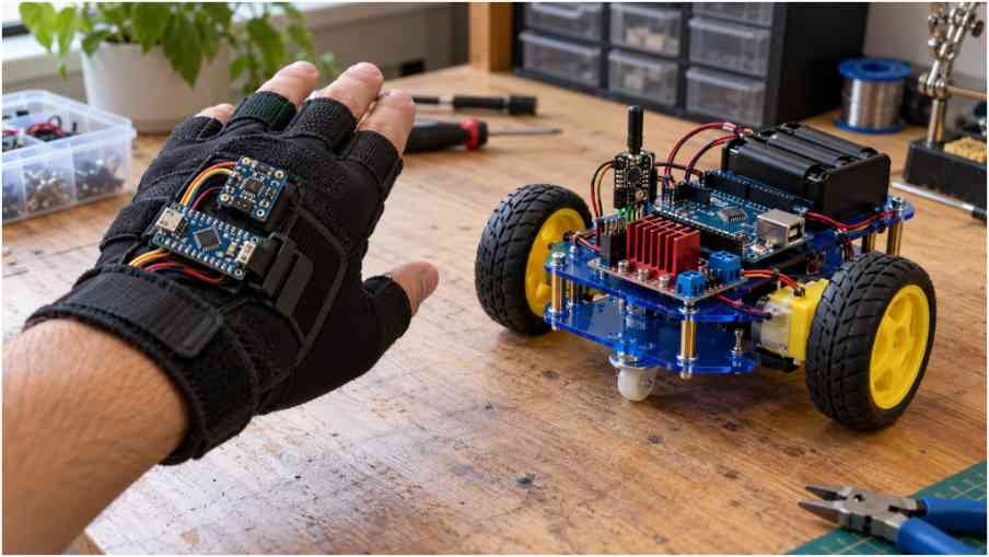
I approach the rigid vs flexible robot chassis decision by asking one question: where can movement help, and where will it create problems? A robot crossing a workshop floor needs predictable wheel alignment. A rover climbing over stones needs its wheels to follow changing ground levels. Those requirements can exist within the same machine.
The best structure keeps motors, bearings, and sensors properly supported while allowing deliberate movement where necessary. Understanding that balance helps prevent wasted material, unreliable navigation, and repeated mechanical repairs.
What Makes a Chassis Rigid or Flexible?
A rigid chassis resists bending and twisting under expected operating loads. No real structure is perfectly rigid, but its deformation should remain small enough to preserve important mechanical relationships.
A flexible, or compliant, chassis intentionally deforms in selected areas. That movement might accommodate obstacles, reduce peak contact forces, or allow a robot to change shape.
Flexibility differs from looseness. A designed flexure bends predictably and returns within its intended operating range. A slipping bracket or loose fastener creates uncontrolled movement that usually damages performance.
Stiffness Is Different From Strength
Stiffness describes resistance to deformation. Strength describes resistance to yielding or failure. Toughness concerns how much energy a material absorbs before fracturing.
A component can be strong enough to survive a load yet bend enough to disturb wheel alignment. Likewise, a stiff component can fracture under an impact if its material or geometry cannot tolerate the resulting stress.
When a Rigid Chassis Works Best
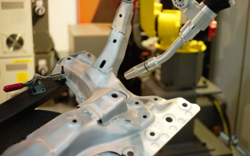
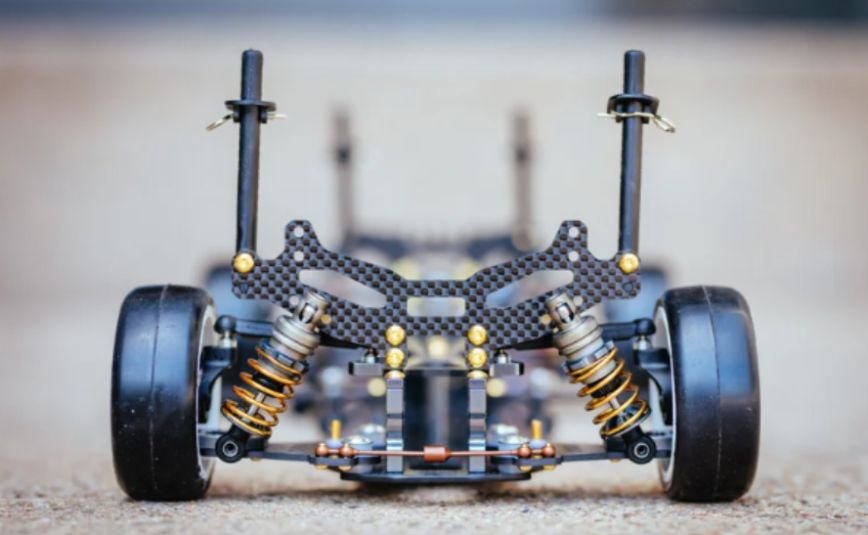
A stiff frame suits robots that need consistent geometry, particularly indoor platforms carrying cameras, lifting mechanisms, or accurately positioned payloads.
Keeping motor mounts and bearing supports aligned helps prevent binding and uneven drivetrain loading. Stable mounting also helps preserve the relationship between navigation sensors and the robot body.
School competition robots, warehouse prototypes, and garage-built inspection platforms commonly benefit from reinforced frames. However, adding material everywhere increases weight and can demand larger motors, batteries, and supporting hardware.
Control Sensor Movement Carefully
Unwanted frame bending can change sensor orientation or position. Vibration can also contaminate measurements.
The solution depends on the sensor and vibration environment. A camera may need a stiff bracket, while an inertial sensor may require carefully selected isolation. Soft mounting without evaluation can introduce additional motion and measurement errors.
When Controlled Flexibility Helps
Intentional compliance can help robots tolerate contact, adapt their shape, or distribute loads across changing surfaces.
For example, a compliant connection between rover sections may permit relative movement over uneven ground. Flexible protective elements can deform during contact while the drivetrain remains supported by a stiff structure.
In the rigid vs flexible robot chassis comparison, location matters more than a simple material label. Flexibility near a protective bumper can be useful; the same movement between coupled bearings may cause misalignment.
Repeated bending also introduces fatigue concerns. Printed polymers may creep under sustained loads, and compliant joints need suitable motion limits, clearances, and cable routing.
Why Suspension Is a Separate Design Choice
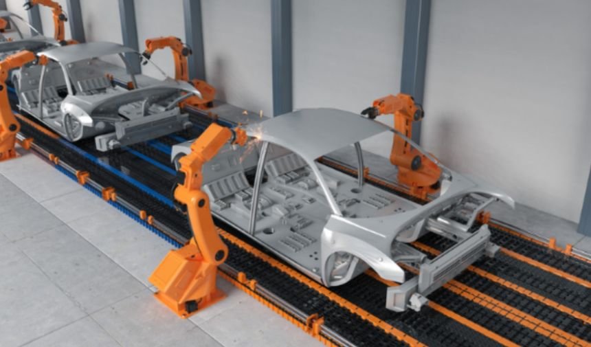
A rigid main frame can handle uneven terrain when suspension or articulated linkages allow the wheels to move independently.
This distinction prevents a common mistake: making the entire chassis bend to keep every wheel touching the ground. An articulated mechanism can preserve a stable electronics platform while accommodating differences in wheel height.
A four-wheel platform without suspension may unload one wheel on uneven ground. Suitable articulation, suspension, or tire compliance can improve contact without sacrificing alignment throughout the frame.
Maintaining wheel contact depends not only on chassis articulation but also on how the robot’s mass is distributed across its support points. If too much weight rests on passive casters or one driven wheel becomes unloaded, the robot may lose traction even when its frame remains structurally sound. Understanding how weight distribution affects robot traction can help you optimise component placement, improve wheel loading, and maintain reliable movement across uneven terrain.
Materials and Geometry Must Work Together
Material choice alone does not determine chassis stiffness. Cross-section, unsupported length, connection design, and loading direction all matter.
Aluminum channels and tubes can provide useful stiffness at manageable weight. Steel can suit heavily loaded structures, although its additional mass affects acceleration and energy requirements.
Printed plastic works well for many lightweight robots when ribs, wall thickness, print orientation, and temperature exposure receive proper attention. Acrylic is convenient for prototypes but can crack around holes and sharp corners.
Reinforce the Load Path
Place heavy batteries near supported regions and keep unsupported spans short. Cross-members and gussets can reduce bending or joint rotation.
Use connections that resist the forces they actually encounter. A single fastener can permit rotation unless other locating features constrain the joint. Check whether reinforcement transfers loads into another weak component.
Chassis stiffness and reinforcement are only part of achieving mechanical stability; the distribution of mass also influences how a mobile robot responds to acceleration, turning, and uneven terrain. Positioning batteries, motors, and other heavy components appropriately helps control load distribution and reduce unwanted shifts in balance.
For a more detailed understanding of these design considerations, see how the center of gravity affects mobile robots, including its implications for stability, traction, and reliable manoeuvring.
How to Test Your Chassis Before Final Assembly

Support the frame in a repeatable arrangement and apply a known load where the payload will sit. Measure displacement relative to a fixed reference using a dial indicator or another suitable measuring tool.
For illustration, a 20-newton load producing 0.5 millimeters of displacement gives a stiffness of 40 newtons per millimeter for that test arrangement. Whether that is acceptable depends on component alignment and operating requirements.
Remove the load and check for permanent deformation. Then test the assembled robot during acceleration, braking, turning, and obstacle crossing.
Evaluating turning performance is another important step in verifying a robot’s chassis geometry and manoeuvrability. Frame deflection, wheel alignment, and the positioning of heavy components can influence how consistently a robot follows its intended path, particularly in confined spaces. Understanding how to calculate a robot’s turning radius helps you estimate the space required for a turn and assess whether your chassis design supports predictable movement without compromising clearance.
Inspect fasteners, wheel contact, sensor mounts, and cable strain afterward.
Frequently Asked Questions
1. Which Wins in the Rigid vs Flexible Robot Chassis Debate?
Choose according to alignment requirements, terrain, payload, and expected impacts. Many practical designs combine a stiff central structure with deliberate movement elsewhere.
2. Does Flexibility Automatically Improve Traction?
No. It helps only when the resulting movement improves wheel contact or load distribution. Poorly controlled bending can disturb steering and drivetrain geometry.
3. How Much Frame Flex Is Acceptable?
There is no universal limit. Establish allowable movement from bearing alignment, sensor accuracy, mechanism clearances, and payload requirements, then verify it under representative loads.
Build Around Your Robot’s Real Loads
I would begin by keeping motor mounts, bearing supports, and sensor brackets stable, then introduce controlled movement where the robot needs it. A platform traveling across smooth floors has different requirements from a rover crossing gravel or uneven thresholds. The right design should reflect those operating conditions, along with payload weight, speed, and expected impacts.
Before committing to the final frame, I would test it with its intended battery, electronics, and payload installed. Watching how it behaves during braking, turning, and obstacle crossing can reveal problems that an unloaded bench inspection misses. Check whether wheels maintain contact, joints shift, cables stretch, or mounting points bend.