
I find robot balance easier to understand when I picture a rover braking with a battery mounted above its wheels. The code may work perfectly, yet the chassis can still pitch forward. That is why I approach center of gravity in mobile robots explained through practical design choices. Battery placement, wheel spacing, payload position, and acceleration all affect whether a robot stays upright.
What Is a Robot’s Center of Gravity?
The center of gravity, or CG, is the point where a robot’s total weight can be considered to act. Its location depends on how weight is distributed throughout the machine.
It does not necessarily sit at the chassis center. A heavy battery behind the wheels pulls it backward, while a tall sensor tower raises it.
For ordinary ground robots, center of gravity and center of mass effectively coincide because gravity varies negligibly across the machine.
How the Support Polygon Determines Balance
Imagine connecting the robot’s ground contact points with straight lines. The enclosed area forms its support polygon.
A three-wheel platform typically has a triangular support area. Four supporting wheels usually create a quadrilateral, although uneven ground can change which contacts carry weight.
Under static conditions, the downward projection of the CG must fall inside this area for tipping resistance. At an edge, the robot reaches the tipping threshold.
Distance matters too. A projection close to an edge leaves less stability margin than one farther inside.
Why Height Matters During Movement

A robot can balance while stationary and still tip during motion. Acceleration, braking, and cornering create overturning effects that grow with CG height.
During braking, load transfers toward the front contacts. During a turn, load transfers toward the outside contacts. A tall robot can unload its opposite wheels sooner, so when you choose the right size for a robot, consider its height, wheelbase, and track width together.
For anyone seeking center of gravity in mobile robots explained, the central lesson is simple: check both component placement and motion commands. Lowering heavy components and limiting acceleration can improve stability together.
What Changes on Slopes?
On a slope, gravity’s downward line meets the supporting surface at a different position relative to the chassis.
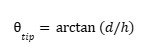
For an ideal rigid robot, the static tipping angle follows:
tip=(d/h)
Here, h is CG height above the support plane, and d is the distance from its projection to the relevant tipping edge. This assumes sufficient grip; sliding may occur first.
How to Calculate Center of Gravity
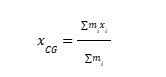
Calculate each coordinate using a mass-weighted average:
xCG=miximi
Repeat for the sideways and vertical coordinates. Use one reference origin and consistent units.
A Simple Battery Placement Example
Suppose a rover has a 1-kilogram chassis assembly centered 6 centimeters above the floor and a 1-kilogram battery centered 18 centimeters high.
Its combined CG height is:

h=(16)+(118)2=12centimeters
Move the battery down to 4 centimeters, and the height becomes 5 centimeters. Total mass stays unchanged, but the lower arrangement improves tipping resistance.
Include motors, brackets, electronics, and payloads when estimating your actual robot. CAD mass properties help when material densities and component models are accurate.
How to Measure a Finished Robot

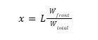
For a platform with front and rear axle lines, place each end on scales at equal height. Measure the wheelbase and both readings. The horizontal CG distance forward of the rear axle is:
x=LWfrontWtotal
A 30-centimeter wheelbase with 40% of the weight supported at the front places the CG 12 centimeters ahead of the rear axle.
This determines fore-aft position, not height. Height requires another method, such as controlled inclined weighing or a suitable suspension measurement. Secure loose parts before measuring.
Improve Stability Without Creating New Problems
Mount batteries and other dense components low while preserving clearance for thresholds and rough surfaces. Widening the wheel track can improve sideways tipping resistance; increasing wheelbase can improve fore-aft resistance.
Weight distribution also affects traction. Moving weight toward driven wheels may improve available grip, but moving it too close to a support edge reduces tipping margin.
Ballast helps when its placement improves the combined CG. Adding weight without changing geometry or CG position does not inherently improve the ideal tipping threshold.
Check movable mechanisms separately. An extended arm or raised payload changes the combined CG. Evaluate the loaded configuration, then use gradual acceleration and braking commands.
Frequently Asked Questions
1. What does center of gravity in mobile robots explained mean for beginners?
It means understanding where the robot’s combined weight acts and how that location affects balance, traction, and tipping during movement.
2. Is the lowest possible center of gravity always best?
A lower CG generally helps conventional wheeled platforms resist tipping. However, ground clearance still matters. Two-wheel balancing robots require a separate analysis involving their controller and pendulum dynamics.
3. Can better tires prevent tipping?
Better traction can reduce slipping, but it does not guarantee tipping resistance. With sufficient grip, a tall robot may tip before it slides. Geometry and motion limits still matter.
4. How should I test stability?
Start slowly on level ground with secured components and a restraint that prevents overturning. Increase demands gradually, stopping at wheel unloading. Repeat checks after changing payloads or component positions.
Build Balance Into the Layout
I would check mass placement before redesigning the control system. A lower battery, better support geometry, or gentler braking may resolve the problem. Calculate the loaded configuration, verify your assumptions, and leave room for uneven surfaces and unexpected movement.