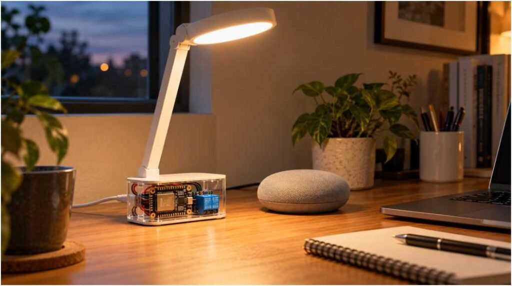
A voice command should turn on your desk lamp without making it flash during startup. My approach to a diy voice controlled desk lamp using esp32 starts with those two goals: reliable switching and predictable behavior.
This build uses a 5V LED lamp, an ESP32, and a relay module. Alexa handles speech recognition, while the ESP32 switches the light. You won’t need a microphone attached to the board.
I recommend proving the voice connection before assembling the enclosure. That catches compatibility problems before you spend time finishing the hardware.
Choose Your ESP32 Voice Control Method
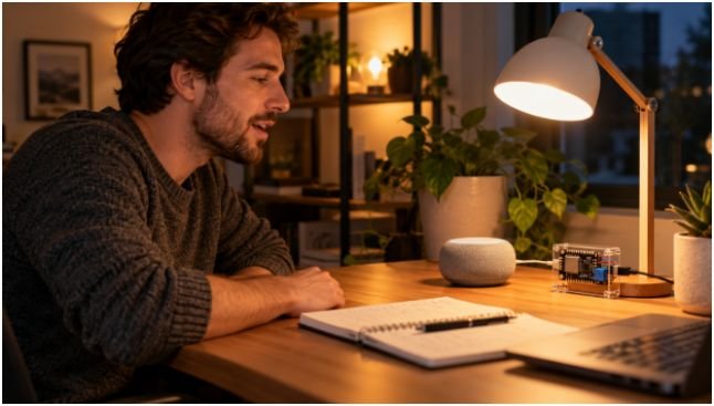
For this project, I’d use Alexa with FauxmoESP. The library emulates a supported lighting device on your local network. However, compatibility can vary with Echo hardware, firmware, and library versions. Treat discovery as an early checkpoint, not a guaranteed outcome. The FauxmoESP project documentation explains its requirements and examples.
Local device communication does not make Alexa voice recognition fully offline. You should still expect internet access for normal Alexa voice operation.
For offline speech recognition, DFRobot’s Gravity DF2301Q module offers built-in and custom commands through I²C or UART. It adds hardware but removes the cloud speech dependency. See the DFRobot voice recognition documentation.
HomeSpan provides another route for Apple Home integration. It supports ESP32 accessories controlled through Apple’s Home app or Siri; Siri’s connectivity requirements remain separate from local accessory control.
These approaches require different software. The code below specifically targets Alexa through FauxmoESP.
Gather the Hardware and Check Power
You’ll need a classic ESP32 DevKit with GPIO23 available, a 5V relay module, and a simple 5V LED lamp. Choose a relay module explicitly compatible with 3.3V control signals. Also gather insulated wire, screw terminals, a multimeter, and an enclosure.
Use a regulated, safety-listed 5V adapter from a reputable supplier. A 2A adapter can suit a small lamp, but the total load determines the requirement.
For example, assume a 3W lamp:
Lamp current = 3W ÷ 5V = 0.6A.
Allowing an illustrative 0.5A for the development board and 0.1A for the relay gives 1.2A total. A 2A supply provides headroom. These are planning allowances, not measured consumption; check your components’ specifications.
Choose a lamp that illuminates whenever power returns. Some touch-controlled USB lamps require another button press after every power interruption.
Before permanent assembly, review your soldering tools for beginner electronics makers.
Wire the ESP32 Relay and 5V Lamp
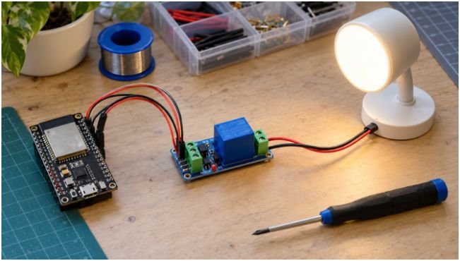
Keep this project entirely on the low-voltage side of the adapter. For a standard household AC desk lamp, use a listed smart plug instead of modifying its mains cord.
Connect the Relay Control Side
Disconnect power before wiring.
Connect relay VCC to the regulated 5V supply and relay GND to the shared ground. Connect GPIO23 to the module’s control input.
The ESP32 uses 3.3V logic. A relay’s 5V coil rating does not prove its input accepts 3.3V safely. Check the module schematic and input specifications against the Espressif ESP32 datasheet. Never allow a 5V input pull-up to drive an ESP32 GPIO.
Power the development board through its documented USB or 5V input. Don’t assume every pin labeled VIN behaves identically. Avoid connecting external 5V and computer USB power together unless the board supports it.
Connect the Lamp Power Circuit
Route the supply’s positive 5V wire to COM on the relay. Connect NO to the lamp’s positive input. Connect the lamp’s negative input directly to supply ground.
Normally open contacts keep the lamp circuit disconnected when the relay is de-energized. They cannot prevent a flash if the control input briefly energizes the relay during boot.
Use suitably rated wire and terminals for the lamp current. Keep lamp current off breadboard power rails, and check the relay’s DC contact rating.
Upload the Arduino IDE Code
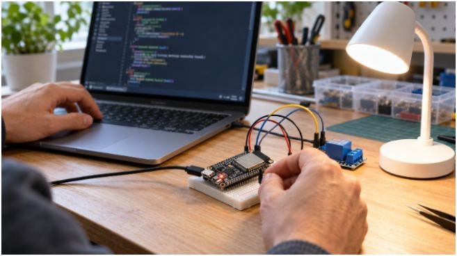
Install ESP32 board support in Arduino IDE. Select your board and port, then install FauxmoESP and its ESP32 AsyncTCP dependency. Check the library’s current example if your installed versions produce compilation errors.
This sketch uses an explicit relay polarity setting. Set ACTIVE_LOW to match your module.
#include <Arduino.h>
#include <WiFi.h>
#include <fauxmoESP.h>
constexpr uint8_t RELAY_PIN = 23;
constexpr bool ACTIVE_LOW = true;
const char* WIFI_SSID = “YOUR_WIFI_NAME”;
const char* WIFI_PASS = “YOUR_WIFI_PASSWORD”;
const char* LAMP_NAME = “Desk Lamp”;
fauxmoESP fauxmo;
void setLamp(bool on) {
digitalWrite(RELAY_PIN,
(on != ACTIVE_LOW) ? HIGH : LOW);
}
void setup() {
Serial.begin(115200);
// Set the output latch to OFF before enabling output.
setLamp(false);
pinMode(RELAY_PIN, OUTPUT);
WiFi.mode(WIFI_STA);
WiFi.setAutoReconnect(true);
WiFi.begin(WIFI_SSID, WIFI_PASS);
unsigned long started = millis();
while (WiFi.status() != WL_CONNECTED) {
if (millis() – started > 20000) {
ESP.restart();
}
delay(100);
}
Serial.print(“IP address: “);
Serial.println(WiFi.localIP());
fauxmo.createServer(true);
fauxmo.setPort(80);
fauxmo.addDevice(LAMP_NAME);
fauxmo.onSetState([](unsigned char id,
const char* name,
bool state,
unsigned char value) {
if (id == 0) {
setLamp(state);
}
});
fauxmo.enable(true);
}
void loop() {
fauxmo.handle();
}
The relay provides on/off switching only. The callback receives a brightness value, but this circuit cannot dim the lamp.
Initializing the output reduces software startup surprises. For reliable boot behavior, the relay input also needs a hardware default that holds it off while the ESP32 resets. Choose its pull-up or pull-down arrangement from the module’s input circuit. A precision screwdriver set also belongs beside the terminal blocks; use the correct bit to avoid damaging their screws.
Connect Your Desk Lamp to Alexa
Connect the ESP32 to a 2.4GHz Wi-Fi network. Keep the Echo on the same local network with device-to-device communication enabled.
Amazon’s smart home connection guidance notes that many Wi-Fi smart home devices require 2.4GHz. The Echo itself may use another band when both bands share the same local network.
After uploading, confirm the IP address in Serial Monitor. Start device discovery through the Alexa app’s device menu, or ask Alexa to discover devices. Menu labels and discovery time can vary.
Once “Desk Lamp” appears, try “Alexa, turn on Desk Lamp,” followed by the off command.
Test Startup Behavior and Fix Common Problems
My acceptance check would cover three states: cold startup, normal voice switching, and network loss.
First, cycle power several times. The lamp should remain off until commanded. A flash suggests an incorrect polarity setting or an unstable relay input during reset.
Next, issue repeated on/off commands. If the relay clicks but the lamp stays dark, check COM/NO wiring and the lamp’s power-return behavior.
If the board resets when switching, measure the 5V rail under load. Check supply capacity, cable resistance, and loose connections.
Finally, disconnect Wi-Fi. This sketch retains the last output state while powered; it does not automatically turn the lamp off during network loss. After a reboot, it starts off.
If discovery fails, check guest-network isolation, local multicast filtering, and FauxmoESP compatibility before changing the wiring. Avoid exposing its local server through router port forwarding.
Make Your Lamp Listen—Without the Drama
I’d finish the enclosure only after the lamp passes its startup and discovery checks. Secure the terminals, add cable strain relief, and keep the ESP32 antenna clear of metal.
Your next step is simple: prove reliable on/off control with the low-voltage lamp. Add brightness control later using a suitable LED driver rather than trying to dim through a relay.
Frequently Asked Questions
1. Can I build a diy voice controlled desk lamp using esp32 without Alexa?
Yes; use an offline voice module or implement another supported smart home platform.
2. Does the ESP32 need a microphone for Alexa control?
No; the Echo captures speech, and the ESP32 receives switching commands.
3. Can a relay dim a 5V LED desk lamp?
No; dimming requires a compatible LED driver and control circuit.
4. Why does my ESP32 relay switch backward?
Its active-high or active-low input behavior likely differs from the code’s polarity setting.