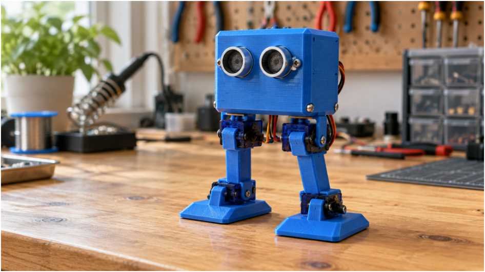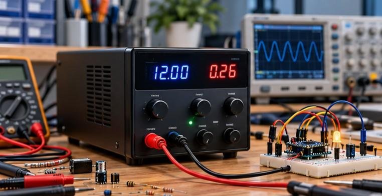
The first sign of a motor-noise problem is often not the motor itself. Instead, an Arduino suddenly restarts, a sensor value jumps for no obvious reason, or a nearby circuit starts behaving unpredictably the moment the motor begins to spin.
That is exactly why DC motor noise matters so much in practical electronics. A DC motor is not just a mechanical load. Inside it, current is being switched rapidly through inductive windings, and those sudden changes can create voltage spikes, electromagnetic interference, and radio-frequency noise. In brushed motors, the brushes and commutator add sparking and brush bounce to the problem, while brushless motors create interference through high-speed electronic switching.
Once I understand where that noise comes from and how it travels through a circuit, it becomes much easier to stop resets, unstable sensor readings, and other frustrating electrical problems.
What Actually Causes Electrical Noise in a DC Motor?
Electrical noise is unwanted voltage or current that appears alongside the useful power and signals in a circuit. In motor systems, this interference may travel through wiring as conducted noise or radiate through the air as electromagnetic interference, commonly called EMI.
The exact cause depends heavily on whether the motor uses brushes or an electronic controller.
Why Do Brushed DC Motors Generate So Much EMI?
How Commutation Sparking Creates High-Frequency Interference
A brushed DC motor uses carbon brushes that slide across a rotating segmented commutator. As the rotor turns, the brushes repeatedly switch current from one winding to another.
The contact is not perfectly smooth.
When a brush leaves one commutator segment and moves onto another, the electrical connection can briefly break or bridge two segments. Current attempts to continue flowing, producing tiny electrical arcs.
These sparks generate short, sharp pulses containing a broad range of frequencies. That energy can escape as radio-frequency interference, or RFI, and can also travel back through the motor’s power wires.
Older motors, dirty commutators, worn brushes, and inexpensive brushed motors may produce even more interference.
Why Inductive Kickback Creates Voltage Spikes
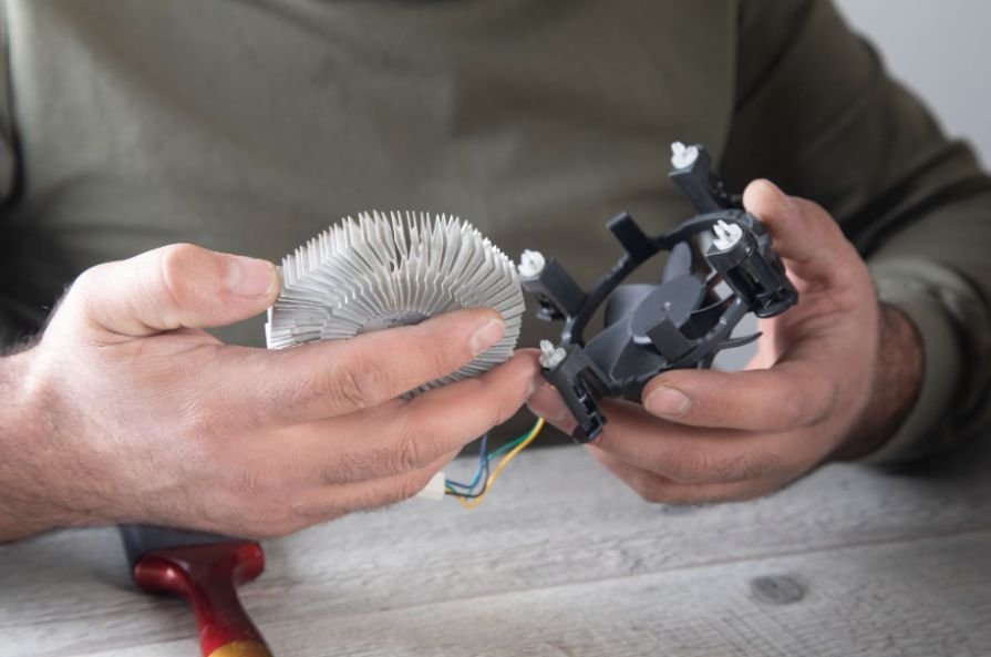
The copper coils inside a DC motor are inductors. An inductor resists sudden changes in current.
Whenever a brush disconnects a winding, the magnetic field around that winding collapses rapidly. The stored magnetic energy must go somewhere, so it can appear as a high-voltage transient.
These inductive voltage spikes can travel back toward the motor driver and power supply.
That is another major reason why a DC motor causes electrical noise even when the motor itself appears to operate perfectly.
How Brush Bounce Makes Motor Noise Worse
Brush bounce is another source that is easy to overlook.
At higher motor speeds, the brushes can vibrate slightly as they move across the commutator surface. Instead of making one clean connection, a brush may rapidly connect and disconnect several times.
Those irregular current interruptions create additional voltage spikes and high-frequency noise.
Mechanical wear, spring pressure, contamination, and commutator condition can all influence brush bounce.
Why Do Brushless DC Motors Still Create Electrical Noise?
Brushless DC motors eliminate mechanical brushes and commutator sparking, but they are not electrically silent.
A BLDC motor relies on an electronic speed controller or motor driver to switch current through its windings.
How PWM and MOSFET Switching Create Noise
BLDC controllers commonly use pulse-width modulation, or PWM, to control motor speed and torque. MOSFETs turn the motor current on and off thousands of times per second.
These fast switching edges resemble square waves rather than smooth DC.
Rapid voltage and current transitions create high-frequency harmonics that can spread through the power rail or radiate from motor and controller wiring.
So brushed motors mainly suffer from mechanical commutation noise, while BLDC systems generate much of their interference electronically.
How Does Motor Noise Reach Microcontrollers and Sensors?
Motor interference can reach other electronics in two primary ways.
What Is Conducted Motor Noise?
Conducted noise travels through wiring.
If the motor and microcontroller share a power supply, fast motor current changes can disturb the common voltage rail. Noise can also travel through ground connections.
Long wires, undersized conductors, poor grounding, and weak power supplies can make the problem worse.
What Is Radiated Motor Noise?
Motor wires can act like antennas.
Fast current changes create changing electromagnetic fields around those wires. Nearby sensor leads, communication cables, or PCB traces can pick up the interference.
This is why even a circuit with separate power regulation may still suffer from motor EMI.
When investigating unstable sensor readings caused by motor interference, it helps to understand how microcontrollers interpret changing electrical signals.
This resource about reading a potentiometer with a microcontroller explains how analog voltages are converted into digital values and why electrical noise can affect measurement stability. Understanding the relationship between input voltage and ADC readings makes it easier to identify whether erratic values originate from interference, power fluctuations, or the signal itself.
Why Does a DC Motor Reset an Arduino or Microcontroller?
A motor-related reset is not always caused by EMI alone.
DC motors can draw several times their normal running current during startup. A stalled motor can draw even more.
If the power supply cannot provide that sudden current, its output voltage may drop. The microcontroller can then experience a brownout and restart.
I always distinguish between a high-frequency noise problem and a power-supply problem.
Short spikes, ringing, and erratic sensor values usually suggest EMI. A noticeable voltage drop when the motor starts often points to inadequate current capacity, excessive wiring resistance, or insufficient bulk capacitance.
Both problems can occur simultaneously.
How Can You Reduce DC Motor Electrical Noise?
Should You Put a Capacitor Across the Motor Terminals?
One of the most effective first steps is placing a small ceramic capacitor directly across the motor terminals.
A 0.1 µF, or 100 nF, ceramic capacitor is a common starting value for small brushed motors.
High-frequency noise sees the capacitor as a low-impedance path, allowing much of that energy to circulate locally rather than travel down the power wiring.
Physical placement matters. I keep the capacitor leads short and position the component as close to the motor terminals as practical.
Some designs also use capacitors between each motor terminal and the metal motor casing to reduce common-mode interference.
Do Flyback Diodes Stop Motor EMI?
Flyback diodes protect switching devices from inductive voltage spikes when current through the motor is interrupted. However, a diode does not automatically eliminate high-frequency brush arcing or switching interference. That means flyback protection and EMI suppression capacitors solve different parts of the problem.
When controlling a DC motor with a microcontroller, selecting an appropriate switching circuit is essential for protecting the control pin and managing the load current.
This beginner-friendly guide to a simple transistor switch circuit explains how a transistor can act as an electronic switch between a low-power control signal and a higher-current load.
Understanding this switching arrangement helps clarify the role of driver components in motor-control circuits, alongside the separate measures needed to suppress electrical noise.
In more demanding motor-control systems, an active EMI filter may also be used to suppress conducted interference across a wider range of operating conditions. Many reliable motor circuits combine flyback protection, capacitors, filtering, and careful wiring for better overall noise control.
Can Ferrite Beads and Chokes Reduce Motor Noise?
Ferrite beads and choke coils help resist high-frequency interference while allowing normal motor current to pass.
They can be especially useful when noise continues traveling through the motor leads after capacitors have been installed.
Why Does Twisting Motor Wires Help?

Twisting the positive and return motor wires keeps opposite current paths close together.
Their magnetic fields partially cancel, reducing radiated interference.
Short motor wiring also helps reduce the antenna effect.
How Should You Improve Power and Grounding Around a DC Motor?
Local decoupling capacitors near microcontrollers and motor drivers help stabilize the supply voltage.
Small ceramic capacitors respond quickly to high-frequency disturbances, while larger electrolytic or low-ESR capacitors help with slower voltage dips and motor startup current.
Good PCB layout also matters. I keep high-current motor paths away from sensitive analog traces and communication lines whenever possible.
For beginner electronics projects, careful component placement and organized wiring can help prevent avoidable connection errors and reduce some sources of interference.
The best breadboard layout for beginner circuits explains how to arrange components and power connections more systematically.
When experimenting with DC motors, keep high-current motor wiring separate from sensitive signal connections and remember that a tidy breadboard layout must be paired with appropriate motor-driver protection, decoupling, and noise suppression.
For demanding systems, separating motor power from logic power can greatly improve stability, provided the grounding and reference scheme is designed correctly.
Frequently Asked Questions
1. Why does a DC motor create EMI?
A brushed motor creates EMI because its brushes repeatedly make and break electrical contact with the commutator. Arcing, inductive voltage spikes, and brush bounce generate high-frequency interference.
2. Can a DC motor damage a microcontroller?
Voltage spikes and poor power design can stress or disrupt a microcontroller. Proper motor drivers, flyback protection, capacitors, decoupling, and grounding help protect the logic circuitry.
3. What size capacitor is commonly used on a DC motor?
A 0.1 µF ceramic capacitor is a common starting point for small brushed DC motors, although the ideal value depends on the motor, driver, and EMI requirements.
4. Why does my sensor reading change when the motor starts?
Motor EMI can couple into sensor wiring or shared power and ground connections. Startup current may also cause a temporary supply-voltage drop.
5. Is a brushless motor quieter electrically than a brushed motor?
A BLDC motor eliminates brush and commutator arcing, but its electronic controller still creates PWM and MOSFET switching noise.
Final Thoughts
Once I understand why a DC motor causes electrical noise, diagnosing unstable electronics becomes much easier. Brushed motors create interference through commutation sparks, inductive kickback, and brush bounce, while brushless motors generate substantial switching noise through PWM-controlled MOSFETs.
The best solution is rarely one component alone.
A well-designed motor system combines suppression capacitors, flyback protection, ferrite filtering, twisted wiring, short current paths, good grounding, sufficient power-supply capacity, and proper decoupling.
When I treat motor EMI and voltage sag as separate but related problems, I can troubleshoot microcontroller resets, noisy sensors, and unstable communication far more accurately and build motor-driven electronics that operate reliably.