A breadboard can make electronics incredibly easy to learn, but a messy layout can turn even a simple LED circuit into a frustrating puzzle. When I build beginner projects, I focus just as much on physical organization as I do on the circuit diagram. The best breadboard layout for beginner circuits keeps power connections obvious, components grouped logically, and jumper wires short enough to trace at a glance.
For beginners in the US learning electronics, Arduino, or basic prototyping, these habits make circuits easier to build, troubleshoot, and expand without creating confusing “spaghetti wiring.”
How Should a Beginner Breadboard Be Organized?
A clean solderless breadboard works best when I treat it as a set of clearly defined zones rather than an open space where components can go anywhere. This same organized approach also helps when learning how to test a capacitor with a multimeter, because clear component placement makes it easier to identify terminals and isolate parts for testing.
Most standard breadboards have outer power rails, two central terminal areas, and a groove running through the middle. Understanding how these sections connect internally helps prevent accidental short circuits and misplaced components.
How Should I Use the Power Rails?
The long outer columns, usually marked with a red plus sign and a blue or black minus sign, are designed for power distribution.
I normally reserve the red rail for positive voltage and the blue or black rail for ground. Keeping these rails dedicated to power makes the entire breadboard easier to read.
I avoid using these rails as general-purpose component rows. Instead, I run short jumper wires from the rails to whichever part of the circuit needs power.
One important detail is that some breadboards have split power rails. The top and bottom sections may not be electrically connected. I always check the markings or test continuity with a multimeter before assuming that one rail runs the full length of the board.
How Are Breadboard Rows A–E and F–J Connected?
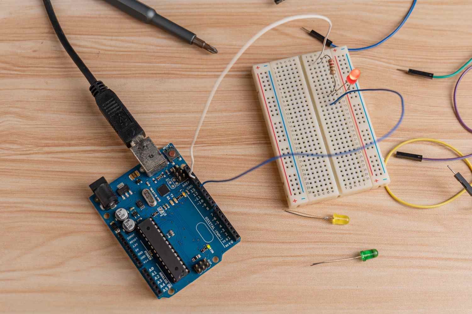
The central terminal area is usually divided into rows labeled A through E on one side and F through J on the other.
Within each numbered row, the five holes on one side are typically connected horizontally. The five holes on the opposite side form a separate connection.
This means component placement matters.
If both leads of a resistor, LED, or another component are placed into holes that share the same connected strip, the component may be bypassed or shorted. I make sure component legs span separate electrical rows unless I intentionally want those points connected.
Why Does the Center Gap Matter on a Breadboard?
The groove down the center is especially important when working with DIP integrated circuits.
I place IC chips straight across this divider so the pins on one side remain electrically isolated from the pins on the other side.
This layout works for many timers, logic chips, microcontrollers, and other dual-inline components.
I also leave enough room around an IC for resistors, capacitors, and jumper wires. Crowding components too tightly may save space, but it makes troubleshooting much harder.
What Wire Colors Should Beginners Use?
Wire color does not change how a circuit works electrically, but consistent color coding makes a huge difference when debugging.
I use red strictly for positive voltage and black or blue for ground. For signal connections, I usually use colors such as yellow, green, orange, or white.
This system allows me to identify power, ground, and signal paths almost instantly.
It also helps when I compare the physical breadboard wiring to a schematic or breadboard diagram.
How Can I Reduce Jumper Wires on a Breadboard?
One of the easiest ways to make a breadboard look cleaner is to avoid unnecessary jumper wires.
When two component leads are supposed to share the same electrical node, I try to place them in the same connected terminal strip whenever practical.
For example, instead of connecting a resistor to an LED using a long jumper wire, I may position the resistor lead and LED lead within the same five-hole row.
This creates a direct electrical connection without an extra wire.
However, I only do this when the circuit actually requires those points to connect. Understanding the internal breadboard layout comes before trying to minimize wires.
Should Breadboard Jumper Wires Be Short?
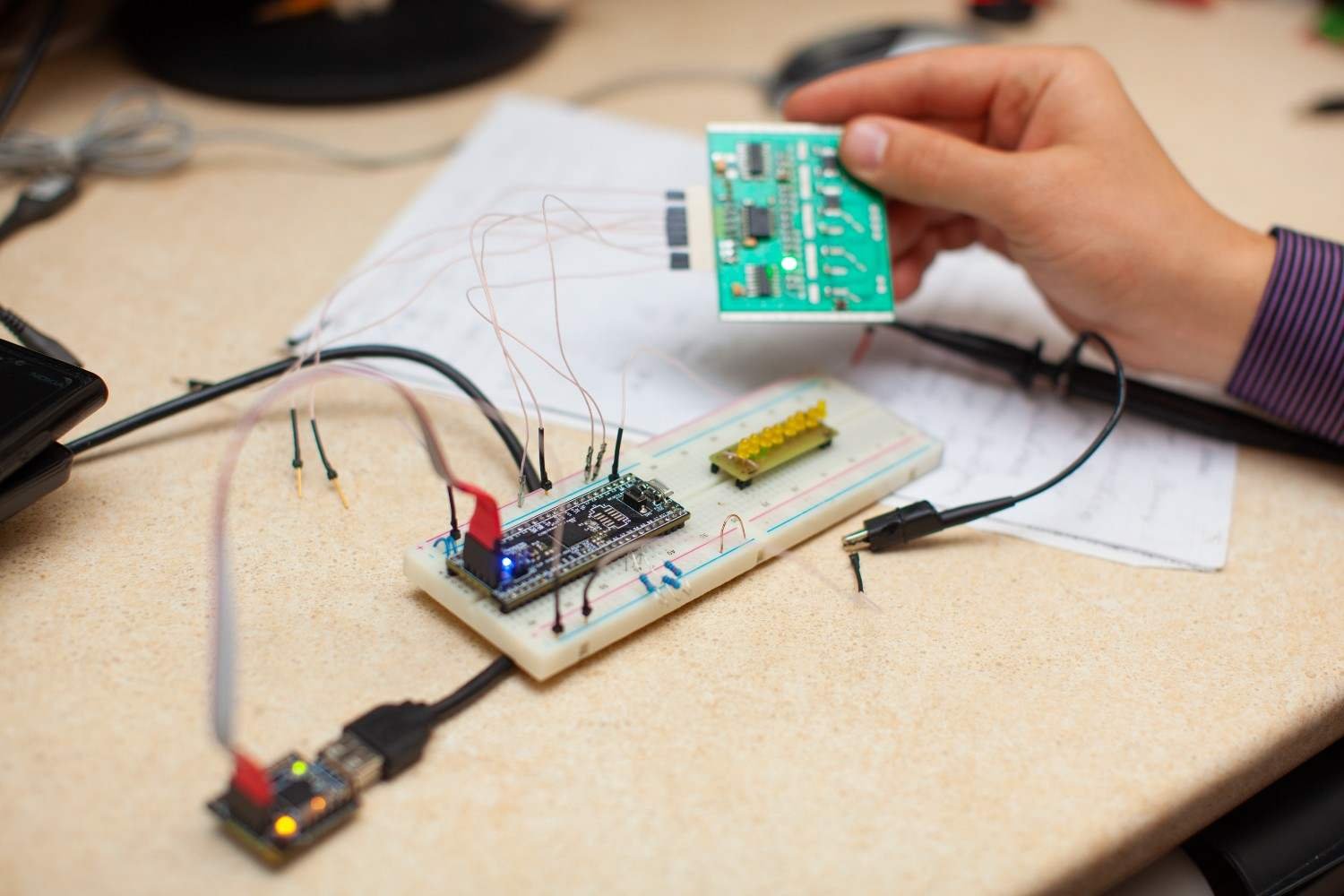
For most beginner electronics circuits, shorter jumper wires are better.
I choose wires that comfortably reach their destination without stretching or looping across the board. Long jumper wires can cover components, cross other connections, and make a simple project look far more complicated than it really is.
If I need a longer wire, I often route it around the edge instead of directly across the middle of the project.
Keeping wires flat and organized also makes it easier to spot loose connections or accidental shorts.
What Is the Best Layout for a Simple LED Circuit?
An LED and resistor circuit is one of the best projects for learning clean breadboard placement.
I start by preparing the positive and ground rails. I then place the LED in the central terminal area with each leg in a separate connected row.
The longer LED leg is typically the anode, which connects toward positive voltage, while the shorter cathode connects toward ground.
I place a current-limiting resistor in series with the LED. For many common 5-volt beginner projects, a resistor around 220 or 330 ohms may be appropriate depending on the LED specifications.
I keep the resistor, LED, and related wires close together so I can visually follow the entire current path.
How Should I Place a Pushbutton on a Breadboard?
Four-leg tactile switches can confuse beginners because some pins are already internally connected.
I typically position a pushbutton across the center divider. This orientation separates its connections and makes the switching action much easier to understand.
If the button controls an LED, I arrange the button, resistor, and LED in a logical sequence rather than scattering them around the board.
A layout that visually follows the circuit path is easier to troubleshoot than one that simply uses the nearest empty holes.
Why Should You Connect Power Last?
This is one rule I never skip.
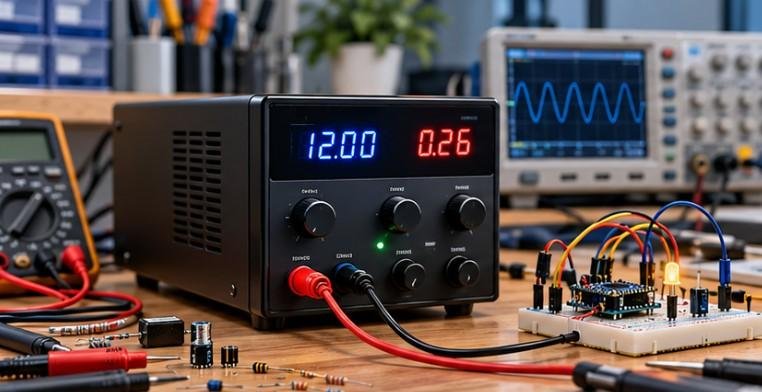
I build the entire breadboard with the battery, USB supply, or bench power supply disconnected.
Once the components and jumper wires are in place, I check the polarity, component rows, power rails, ground connections, and possible short circuits.
Only then do I connect power.
This habit helps protect LEDs, ICs, sensors, microcontrollers, and other components from wiring mistakes.
What Breadboard Layout Mistakes Cause Circuits to Fail?
Many beginner problems come from misunderstanding the breadboard rather than choosing the wrong components.
Common issues include putting both component legs in the same connected strip, reversing LED polarity, forgetting that power rails may be split, placing a pushbutton in the wrong orientation, or accidentally connecting positive voltage directly to ground.
Loose jumper wires can also cause intermittent problems.
Whenever a circuit fails, I troubleshoot one section at a time instead of rewiring everything immediately.
How Do I Keep Larger Breadboard Circuits Easy to Troubleshoot?
As circuits grow, I separate them into functional areas.
I might keep power distribution near one edge, input components such as buttons or sensors toward one side, processing components in the center, and LEDs, motors, or other outputs toward the opposite side.
I also leave unused rows between sections when space allows.
The goal is not to create the smallest possible circuit. The goal is to create one that I can understand five minutes—or five days—after building it.
FAQs About Beginner Breadboard Layouts
1. What is the easiest breadboard circuit for a beginner?
An LED with a current-limiting resistor is one of the easiest starting projects. It teaches polarity, power rails, connected rows, jumper wiring, and basic component placement.
2. Do breadboard components have to cross the center gap?
No. Most individual components can sit anywhere across electrically appropriate rows. DIP integrated circuits and some switches are commonly placed across the center gap.
3. Can I put components directly into the power rails?
It may work electrically in some cases, but I prefer keeping power rails dedicated to voltage and ground distribution. This makes the layout more consistent and easier to debug.
4. Why are my breadboard power rails not working?
Some boards split the rails into separate sections. A jumper may be required to connect the sections. Check the markings or test continuity with a multimeter.
5. How do I know which breadboard holes are connected?
On most common boards, groups of five holes in each terminal row are electrically connected, while the center gap separates the two sides. Power rails usually run vertically along the outer edges.
Final Thoughts
The best breadboard layout for beginner circuits is not about squeezing every component into the smallest possible area. I get better results when I separate power from signal wiring, color-code connections, use direct terminal-strip connections when appropriate, keep jumper wires short, place ICs across the center divider, and connect power only after checking the finished circuit.
Once these habits become automatic, the best breadboard layout for beginner circuits becomes easier to reproduce across LED projects, sensor circuits, Arduino experiments, switches, transistors, and other beginner electronics builds.