Chasing the perfect fit for your custom desktop robotics project can feel incredibly frustrating when parts refuse to snap together. You design a gorgeous robotic arm joint in computer aided design programs, wait hours for the machine to finish, and realize the motor shaft will not slip into the plastic housing.
Dealing with plastic parts that expand or shrink unexpectedly is a rite of passage for every maker. Learning how to measure 3d print accuracy is simply about using the right physical tools and adjusting a few hidden settings inside your slicing software.
The Ultimate Quest for Flawless Robot Joints
Why learn how to measure 3d print accuracy now? Because building custom robots is a billion times cooler when your gears mesh beautifully rather than jamming up and melting your expensive servo motors!
Necessary Gear for Precise Spatial Verification
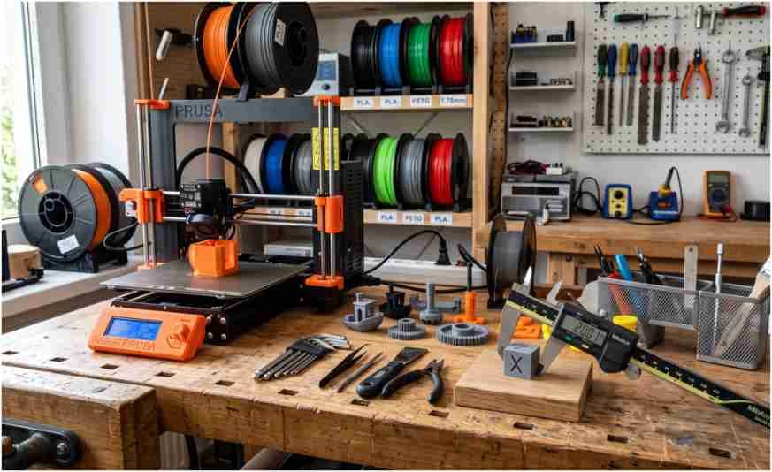
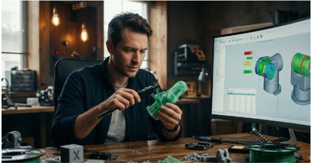
You cannot fix an error that you are unable to calculate properly down to the millimeter. Investing in a decent pair of digital vernier calipers is the single best choice you can make for your workshop.
Standard plastic rulers or flexible tape measures are completely useless here because they cannot capture the tiny decimal deviations that cause mechanical joints to bind up. Calipers let you check internal openings, outer walls, and hole depths with extreme precision down to a fraction of a millimeter.
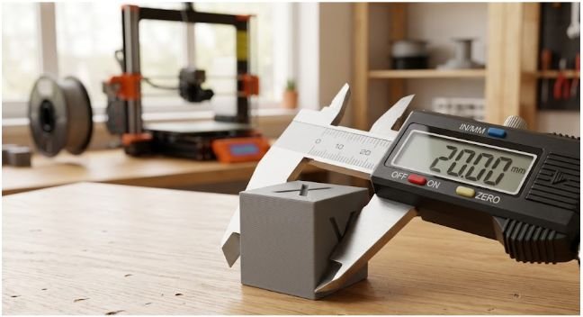
Using your fresh calipers requires a gentle touch so you do not accidentally create false readings. Plastic is inherently soft, meaning if you squeeze the metal jaws down too hard on the part, the material compresses and throws off your data.
Always zero the tool while the jaws are fully closed before starting a measurement session. Slide the jaws until they just whisper against the plastic edges, take three separate readings at different spots, and use the average value.
Printing Benchmark Models to Uncover Machine Deviations
Printing a specialized test object is the fastest way to see where your machine is drifting out of alignment. The classic twenty millimeter calibration cube is the absolute gold standard for diagnosing basic spatial errors. This tiny open source block features clearly engraved letters for the X, Y, and Z axes so you know exactly which motor is causing trouble.
A perfectly calibrated machine will spit out a cube that reads exactly twenty millimeters on every single face when checked with your calipers.
Getting a clean diagnostic run means slicing the cube with specific, neutral parameters. Use your standard layer height, set the infill to zero percent, and turn off top solid layers to create a hollow shell.
Evaluating the Dimensional Data Against Digital Designs
Once the benchmark print cools down entirely, it is time to run the raw numbers. Carefully measure the distance across each axis face while avoiding any embossed text that could lift the caliper jaws.
Compare your real world numbers against the original twenty millimeter digital model files to find the exact structural variance. A variance of less than point one to point two millimeters is considered excellent for basic fused deposition modeling machines.
Understanding this variance tells you whether the machine is suffering from a mechanical issue or a simple software miscalculation. If your cube measures twenty point four millimeters on every single side, your machine is scaling things up evenly.
If only the X axis is short, you know the mechanical belt might be slipping during quick movements. This targeted data collection prevents you from guessing wildly while trying to fix your machine calibration.
Diagnostic Tests Using Single Wall Shell Geometry
Isolating the behavior of your melting thermoplastic requires looking at a single line of extrusion. Slicing an open top cube with one single perimeter wall gives you the ultimate view into your true material flow.
Set your slicer to a specific extrusion width like point four millimeters and print the test object. This method removes variables like internal infill overlapping, which often distorts the outer shell dimensions of your robotics housings.
Measure the thin walls gently with your digital calipers at multiple spots along the upper edges. If your tool displays point forty eight millimeters instead of point four, your nozzle is pushing out way too much material.
This extra width creates thick parts that refuse to fit together smoothly during final assembly. This simple test pinpoints extrusion issues before they ruin complex multi part builds.
Calibrating Hardware Stepper Motor Configurations
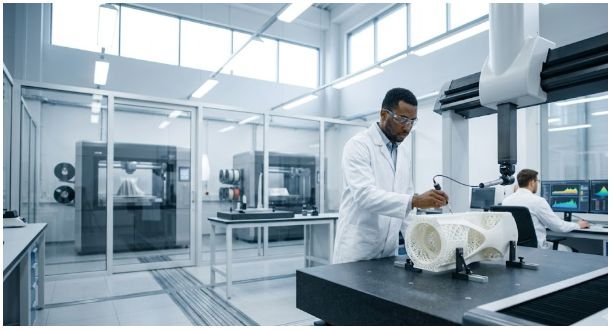
When your physical prints are off by a consistent percentage over large distances, hardware adjustments are required. The stepper motors driving your belts rely on a specific number of electrical steps to move the toolhead one millimeter. You can calculate the required changes using a straightforward ratio formula:
$$\text{New Steps/mm} = \text{Current Steps/mm} \times \frac{\text{Expected Dimension}}{\text{Measured Dimension}}$$
This math allows you to update your mainboard configurations accurately.
Flashing these updated values into your printer firmware ensures the physical travel matches the digital commands perfectly. Programs like Marlin or Klipper allow you to save these motor values directly to the onboard memory.
Be careful to only change these settings after ensuring your belts are perfectly tight. Tuning the firmware steps is highly effective for fixing long-distance scaling errors across your robot chassis.
Using the best 3D printer for robotics projects also contributes to better mechanical accuracy, as a well-calibrated printer produces dimensionally precise parts that fit together correctly, reducing the need for excessive firmware adjustments and improving the overall performance of your robotic builds.
Micro Tuning Extrusion Flow Inside Slicing Programs
Adjusting the extrusion multiplier within your software is the safest way to fix minor wall thickness errors. If your single wall diagnostic cube proved that your plastic lines are printing too wide, simply reduce the flow percentage.
Dropping the flow rate from one hundred percent down to ninety five percent slims down the plastic bead immediately. This soft fix does not require messing with dangerous firmware code or updating mainboard files.
Tuning the flow rate ensures that internal holes and outer perimeters match your digital workspace specifications. When the nozzle extrudes the exact correct volume of plastic, layers stack cleanly without creating ugly bumps or ridges.
This creates smooth internal surfaces that allow structural metal pins to slide into place without requiring extra drilling. It is the easiest shortcut to professional grade fits for custom robotics linkages.
Using Horizontal Expansion to Solve Tight Internal Fits

Internal openings like bolt holes almost always print slightly smaller than your original digital blueprints. As the hot plastic nozzle moves in a tight circle, the cooling material naturally pulls inward toward the center.
Slicers like Ultimaker Cura and PrusaSlicer include a setting called horizontal expansion or XY size compensation to combat this mechanical trait. This tool offsets the paths of the nozzle automatically based on your specific settings.
Entering a small negative value like minus point one millimeter instructs the slicer to trim the outer edges slightly. This leaves the overall scaling of your part accurate while opening up tight internal clearances perfectly.
It allows you to design your parts using true real world dimensions in your engineering software. The slicing engine handles the complex math needed to compensate for the natural behavior of melting polymers.
Frequently Asked Questions
1. How to measure 3d print accuracy?
You must print a benchmark object like a calibration cube and measure the cooling plastic faces using precise digital calipers. Compare the physical values against your digital CAD model dimensions to calculate the exact spatial variance of your machine.
2. Is 100% infill stronger than 50%?
Yes, it adds extra material mass, but the strength returns diminish past seventy percent. For robotics projects, adding extra outer wall loops provides massive structural durability gains while saving tons of filament and printing time.
3. What is the 45 degree rule in 3D printing?
This classic rule states that any overhanging model angle shallower than forty five degrees can print cleanly without breakaway support structures. Steeper angles will droop or fail completely because the molten plastic lacks enough underlying layer support.
4. Is 0.2 mm layer height good?
It is the absolute sweet spot for everyday functional printing. This height delivers an excellent balance of clean surface detail, strong layer adhesion, and rapid print speeds for structural robotic assemblies.
The Winner Circle: Flawless Assembly on the First Try
Taking control of how to measure 3d print accuracy transforms the way you approach custom robotics design. Ditching the basic workshop ruler for digital calipers and mastering flow rate adjustments removes all the frustrating guesswork.
Your custom gears, motor mounts, and electronics enclosures will finally fit together exactly like they do on your computer screen. Keep practicing, calibrate your favorite filaments regularly, and enjoy the confidence of printing parts that assemble flawlessly on the very first try.