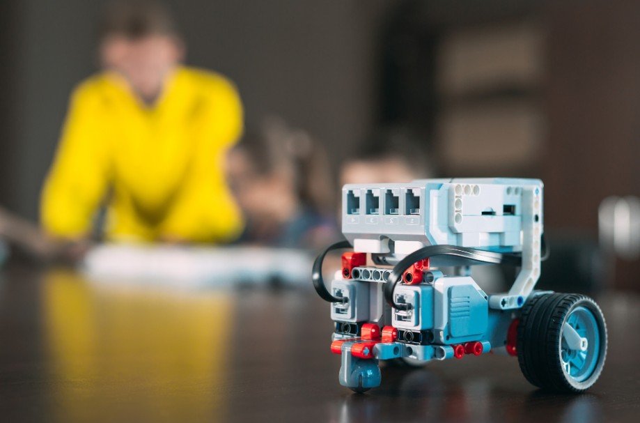
I still remember how satisfying it felt to send the first command from my phone and watch a small robot roll across the floor. The project looks technical at first, but it becomes manageable when the wiring, power supply, code, and controls are handled in the right order.
In this guide, I explain how to make a bluetooth controlled robot using an Arduino Uno, HC-05 module, L298N motor driver, and a two-wheel chassis.
How the Bluetooth Robot Works
A phone sends single-character commands through Bluetooth. The HC-05 receives them and passes them to the Arduino through serial communication. The Arduino then tells the L298N motor driver which motors should run and in which direction.
This basic build operates without continuously checking whether the robot has reached the intended speed, direction, or position. Understanding open loop vs closed loop robotics key differences helps explain how future upgrades such as wheel encoders, feedback sensors, and automatic speed correction can make the robot more accurate.
A simple command system uses F for forward, B for backward, L for left, R for right, and S for stop. This keeps the code easy to understand and works with many Android Bluetooth controller apps.
Parts and Tools You Will Need
Use an Arduino Uno, HC-05 Bluetooth module, L298N motor driver, two geared DC motors, two wheels, one caster wheel, a 2WD chassis, jumper wires, a battery holder, an on-off switch, screws, and spacers. A screwdriver, wire stripper, electrical tape, and soldering iron are also useful.
Choose a battery pack that can supply enough current for both motors. A four- or six-AA holder, or a protected rechargeable pack suited to the motors, is usually more dependable than a small rectangular 9V battery. Never power the motors directly from the Arduino 5V pin.
Assemble the Robot Chassis
Attach the Motors and Wheels
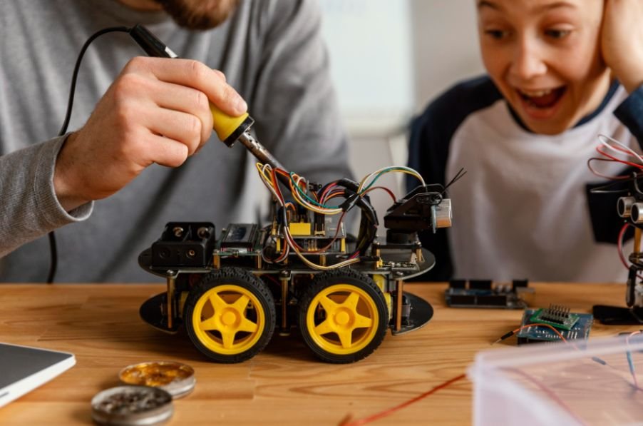
Fix one motor to each side of the chassis. Push the wheels onto the shafts, then install the caster wheel at the front or rear. Make sure the chassis sits level and both wheels rotate freely.
Mount the Electronics
Secure the Arduino, motor driver, battery holder, and HC-05 with spacers, screws, or mounting tape. Keep wires away from the wheels and leave access to the Arduino USB port.
Connect the Arduino, HC-05, and L298N
Connect the left motor to OUT1 and OUT2 on the L298N and the right motor to OUT3 and OUT4. Wire IN1, IN2, IN3, and IN4 to Arduino pins 5, 6, 9, and 10.
Connect HC-05 VCC to 5V and GND to GND. Connect HC-05 TX to Arduino pin 2. Connect Arduino pin 3 to HC-05 RX through a voltage divider because the module’s RX pin uses lower logic voltage.
Connect the battery pack to the motor driver’s power input. Join the grounds of the battery, driver, Arduino, and HC-05. Without a common ground, control signals may behave unpredictably.
Upload the Arduino Code
This sketch uses SoftwareSerial, so the USB connection remains available while the robot communicates with the Bluetooth module.
#include <SoftwareSerial.h>
SoftwareSerial bluetooth(2, 3);
const int IN1 = 5;
const int IN2 = 6;
const int IN3 = 9;
const int IN4 = 10;
void setup() {
bluetooth.begin(9600);
pinMode(IN1, OUTPUT);
pinMode(IN2, OUTPUT);
pinMode(IN3, OUTPUT);
pinMode(IN4, OUTPUT);
stopRobot();
}
void loop() {
if (bluetooth.available()) {
char command = bluetooth.read();
if (command == ‘F’) moveForward();
else if (command == ‘B’) moveBackward();
else if (command == ‘L’) turnLeft();
else if (command == ‘R’) turnRight();
else if (command == ‘S’) stopRobot();
}
}
void moveForward() {
digitalWrite(IN1, HIGH);
digitalWrite(IN2, LOW);
digitalWrite(IN3, HIGH);
digitalWrite(IN4, LOW);
}
void moveBackward() {
digitalWrite(IN1, LOW);
digitalWrite(IN2, HIGH);
digitalWrite(IN3, LOW);
digitalWrite(IN4, HIGH);
}
void turnLeft() {
digitalWrite(IN1, LOW);
digitalWrite(IN2, HIGH);
digitalWrite(IN3, HIGH);
digitalWrite(IN4, LOW);
}
void turnRight() {
digitalWrite(IN1, HIGH);
digitalWrite(IN2, LOW);
digitalWrite(IN3, LOW);
digitalWrite(IN4, HIGH);
}
void stopRobot() {
digitalWrite(IN1, LOW);
digitalWrite(IN2, LOW);
digitalWrite(IN3, LOW);
digitalWrite(IN4, LOW);
}
If forward and backward are reversed, swap the two wires on the affected motor instead of rewriting the program.
Pair the Robot With an Android Phone
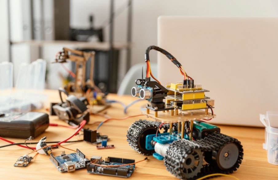
Power the robot and open the phone’s Bluetooth settings. Select HC-05 and enter 1234 or 0000 when prompted. Install a Bluetooth controller app and configure its buttons to send F, B, L, R, and S.
Most HC-05 modules use Bluetooth Classic, which is widely supported by Android. Many iPhones do not communicate directly with HC-05 modules. For broader phone compatibility, consider an ESP32 board using Bluetooth Low Energy.
Test the Robot Safely
Lift the wheels off the ground for the first test. Check every direction, confirm that the stop command works immediately, and verify that the motors rotate evenly. Then test the robot on a clear floor at short range.
If the Arduino resets when the motors start, the battery may be weak or motor noise may be affecting the board. Use a stronger power source, confirm the common ground, shorten loose wires, and add capacitors near the motors when needed.
Easy Project Upgrades
Add PWM speed control through the L298N enable pins, ultrasonic obstacle detection, headlights, a buzzer, line-following sensors, or voice commands.
After mastering phone-based directional control, building a DIY voice controlled robot project is a practical next step because it introduces speech commands while using many of the same motor-control principles.
A custom MIT App Inventor controller can also add speed sliders and dedicated buttons. For a more advanced version, replace the Arduino and HC-05 combination with an ESP32 to reduce the number of components and support Bluetooth Low Energy.
Frequently Asked Questions
1. Can a beginner learn how to make a bluetooth controlled robot?
Yes. It uses basic wiring, simple Arduino functions, and single-character commands, making it suitable for careful beginners.
2. Why does the HC-05 connect but send no commands?
The app may use different command letters, the baud rate may be wrong, or the TX and RX connections may be reversed.
3. Can I use four motors instead of two?
Yes, provided the motor driver and battery can safely supply the total current required by all four motors.
4. How far can the robot travel from the phone?
Indoor range is often several meters, but walls, interference, module quality, and battery condition can reduce it.
Final Thoughts
I like this project because it teaches mechanical assembly, motor control, serial communication, mobile interaction, and troubleshooting in one practical build. Once the basic version works reliably, I would add speed control before decorative features.
Stable power, clean wiring, and a dependable stop command matter more than complexity. With those foundations in place, the same chassis can grow into an obstacle-avoiding, voice-controlled, line-following, or sensor-based robot.