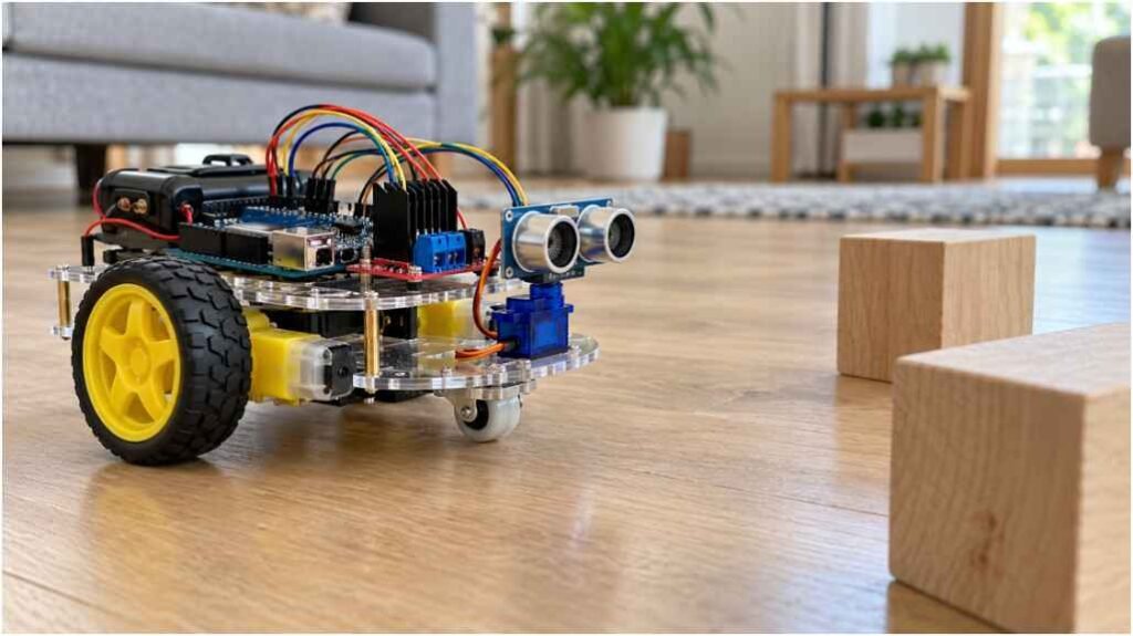
I enjoy robotics most when I can watch a machine respond in real time. Building a diy robot car with obstacle detection combines mechanics, electronics, coding, and problem-solving in one approachable project. The car drives forward, measures the path, stops before a collision, and turns toward a clearer direction.
This guide uses an Arduino, HC-SR04 sensor, micro servo, and L298N driver. It covers wiring, assembly, program logic, calibration, troubleshooting, and upgrades.
How the Robot Avoids Obstacles
The ultrasonic sensor sends a sound pulse and measures how long the returning echo takes. The Arduino converts that duration into distance.
When the path is open, both motors move forward. When an object enters the safety range, the car stops and reverses. The servo points the sensor left and right, letting the Arduino compare both distances and choose the more open side.
Narrow legs, angled surfaces, fabric, and objects outside the sensor beam may produce weak readings, so practical testing matters.
Components and Tools Required
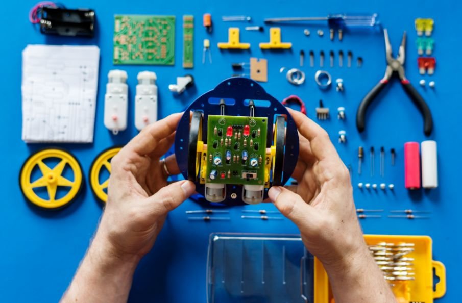
You need an Arduino Uno or Nano, HC-SR04 sensor, L298N driver, micro servo, two geared motors, wheels, caster wheel, chassis, jumper wires, mounting hardware, battery holder, and battery pack.
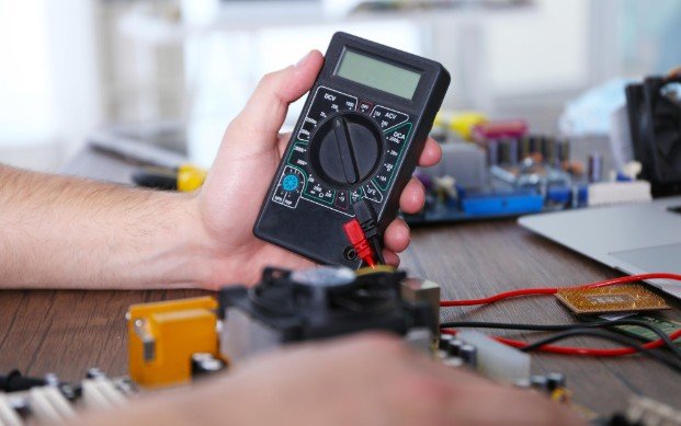
A screwdriver, cable ties, soldering iron, and multimeter are also useful. Some of the same measuring and mounting tools may be used to hang a TV mount, but always select tools suited to the robot’s smaller components.
Never run the motors directly from the Arduino. Power them through the driver and connect the Arduino, driver, servo, and sensor to a common ground. Check the supported voltage of every component before switching on the robot.
Circuit Diagram and Wiring
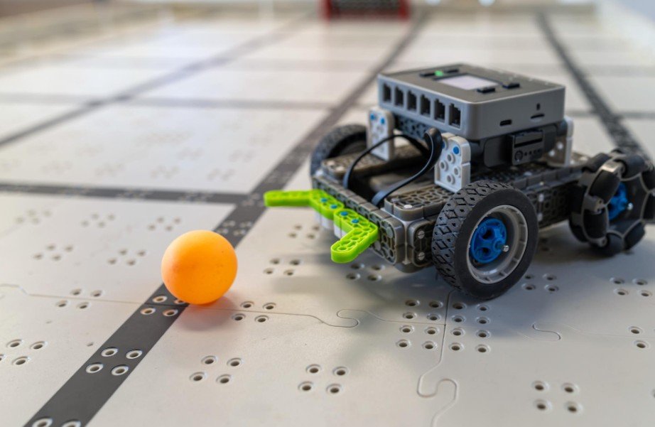
Use a circuit diagram designed for your exact motor-driver module because pin labels can vary. Connect the HC-SR04 trigger and echo pins to two Arduino digital pins. Connect the servo signal wire to another digital pin.
The L298N uses four input pins to control motor direction. Its enable pins accept PWM signals for speed control. Attach each motor to a separate output channel.
The battery powers the motor driver, while the Arduino requires a stable regulated supply. Every module must share a common ground. A missing ground connection often causes false readings, servo shaking, and unpredictable motor movement.
Assemble the Robot Car
Build the Chassis
Secure both motors and ensure the wheels rotate freely without touching the frame. Fit the caster wheel so the platform remains level. Mount the battery near the center to distribute the weight evenly.
Install the Sensor and Boards
Attach the ultrasonic sensor to the servo horn. Position it high enough to avoid detecting the floor but low enough to detect ordinary objects.
Mount the Arduino and motor driver where their USB hardware, pins, and terminals remain accessible. Keep wires short, organized, and away from the wheels.
Test Each Part
Before uploading the complete program, test the motors, servo, and sensor separately. Confirm that both motors can move forward and backward. Move the servo through its left, center, and right positions.
Open the Arduino serial monitor and compare the sensor readings with manually measured distances. Testing individual components makes later faults much easier to locate.
Write the Arduino Navigation Logic
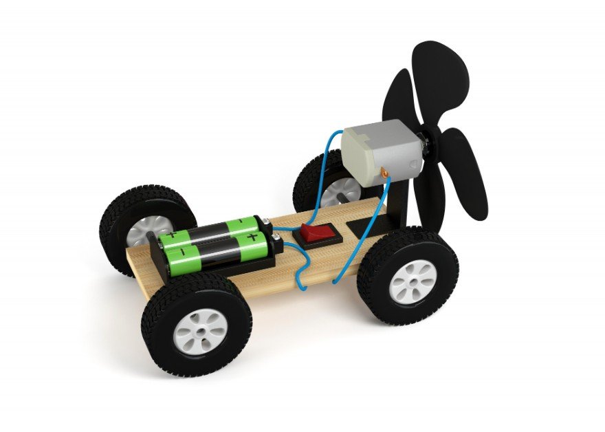
Organize the sketch into functions for moving forward, reversing, stopping, turning left, turning right, and reading distance. This structure keeps the code readable and simplifies troubleshooting.
Learners who want to progress from basic Arduino logic to Python-based control can later explore Raspberry Pi robot projects for beginners, where sensors, cameras, and wireless features can be managed through a more powerful single-board computer.
During setup, define the trigger pin as an output, the echo pin as an input, and the motor-control pins as outputs. Attach the servo and move it to its center position.
In the main loop, read the forward distance. Continue moving when the distance exceeds the safety threshold. When an object is too close, stop, reverse, scan both sides, and turn toward the larger reading.
Add a brief pause after moving the servo. Without this delay, the sensor may record a distance before it reaches the intended angle.
Begin with a detection threshold of 20 to 30 centimeters. The best setting depends on motor speed, wheel grip, chassis weight, and stopping distance.
Test and Calibrate the Car
Start on a clear, level floor at low speed. Place a large box ahead and check whether the robot stops with enough space. Then test walls, narrow objects, angled surfaces, fabric, and tight passages.
If the car drifts, give one motor a slightly different PWM speed. Small DC motors rarely rotate at identical rates. Adjust the turning delay until the robot rotates enough to escape an obstacle without spinning too far.
For unstable sensor values, take several measurements and reject impossible results. Avoid excessive averaging because it can make the robot respond too slowly.
Common Problems and Fixes
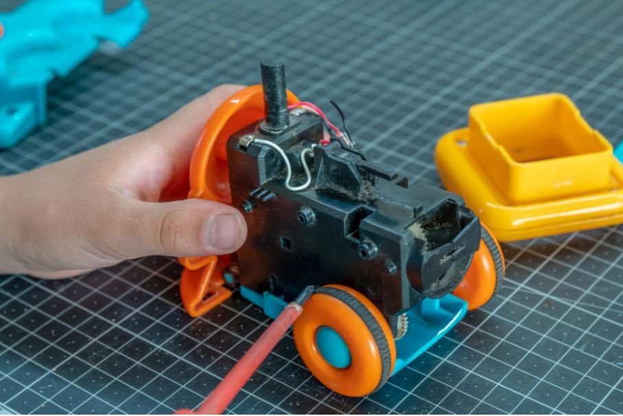
If the motors do not move, inspect the battery charge, driver jumpers, terminals, input pins, and motor voltage.
If one wheel runs backward, swap its wires or reverse its direction commands in the program. If the Arduino resets whenever movement starts, use a stronger power supply and separate motor power from regulated logic power.
Zero or extreme sensor values may indicate incorrect trigger and echo connections, weak grounding, or poor sensor positioning. Servo shaking often means the power supply cannot provide enough current.
When the car turns into obstacles, increase the detection threshold, reduce motor speed, widen the scanning angle, or wait longer before measuring each side.
Upgrade Ideas
After the robot operates reliably, explore other beginner robot projects with sensors to practise using ultrasonic, infrared, light, sound, and motion sensors in different builds. This helps reinforce the same detect-decide-respond logic used by the obstacle-avoiding car.
After the robot operates reliably, add Bluetooth control for switching between manual and autonomous modes. Infrared sensors can detect low objects, while additional ultrasonic sensors can reduce blind spots.
Other useful upgrades include line-following sensors, wheel encoders, lights, a buzzer, an ESP32 camera, battery monitoring, or a small display. Add one feature at a time so new faults remain easy to diagnose.
Frequently Asked Questions
1. Is a diy robot car with obstacle detection suitable for beginners?
Yes. The project is manageable when the motors, servo, sensor, wiring, and power system are tested separately.
2. Can I build the car without a servo?
Yes, but a fixed sensor normally relies on preset turns. A servo lets the controller compare the available space on both sides.
3. Why does the robot detect objects too late?
The motor speed may be too high, the detection threshold may be too low, or long program delays may be slowing sensor updates.
4. Which battery should I use?
Choose a rechargeable pack that matches the motor and driver voltage while supplying enough current for every connected component.
Final Thoughts
I like this build because every adjustment creates an immediate change in the robot’s behavior. Reliable performance depends more on stable power, common grounding, tidy wiring, individual component tests, and careful calibration than on expensive parts.
Once the car can detect, stop, scan, and turn consistently, I would add upgrades gradually. That approach makes troubleshooting easier and turns a simple moving chassis into a flexible platform for learning autonomous robotics.